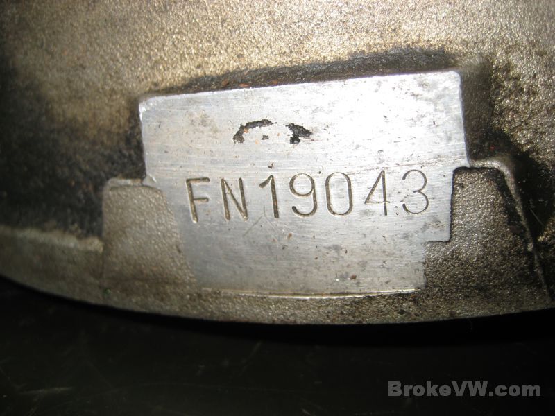
Bob P. FN19043
Arrived 11/10/11 - Done 03/14/12
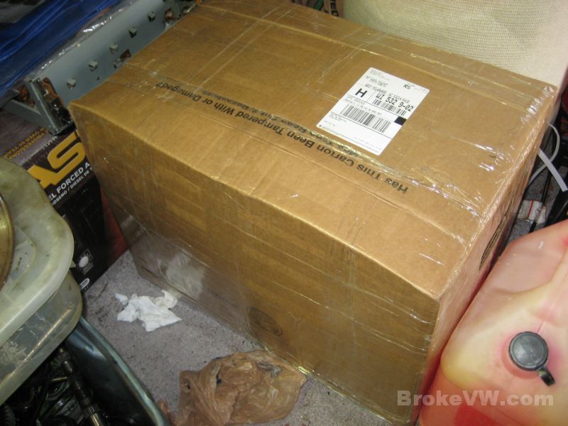
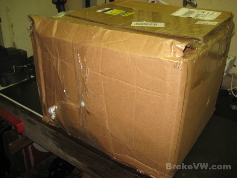
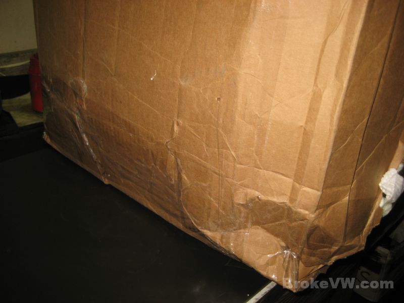
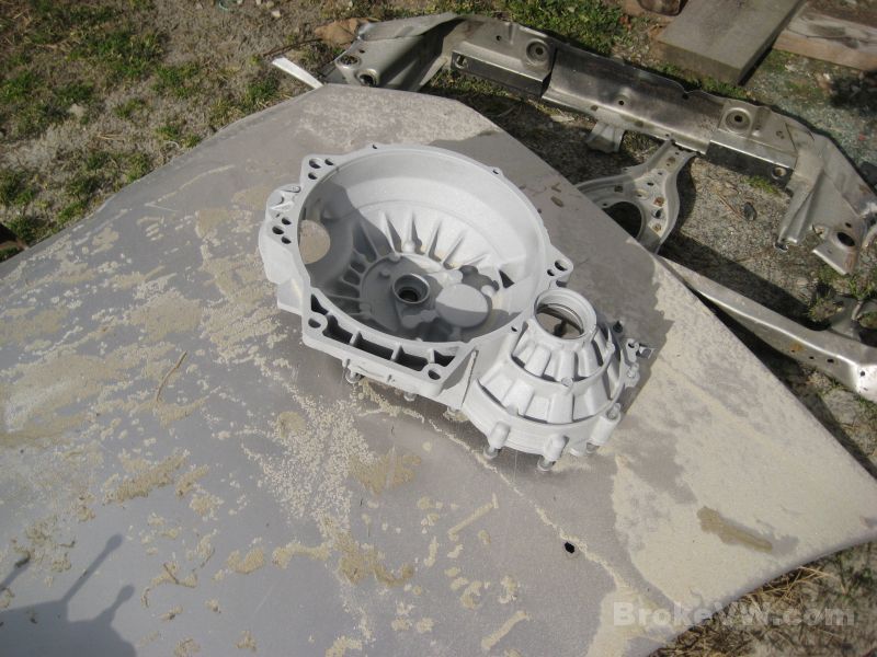
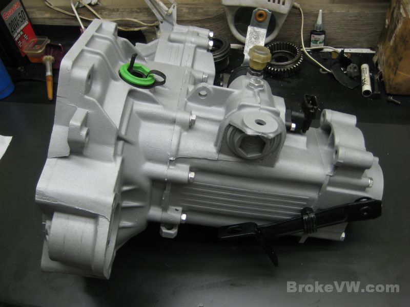
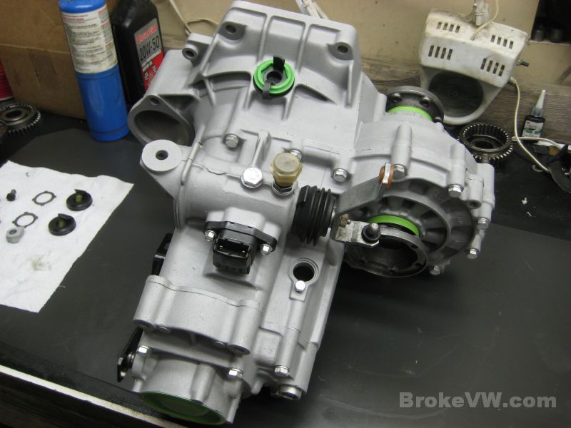
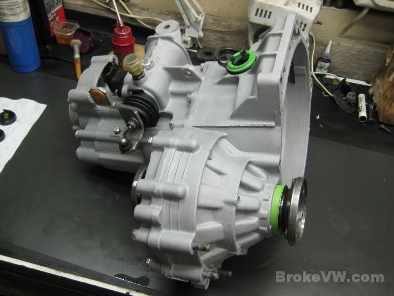
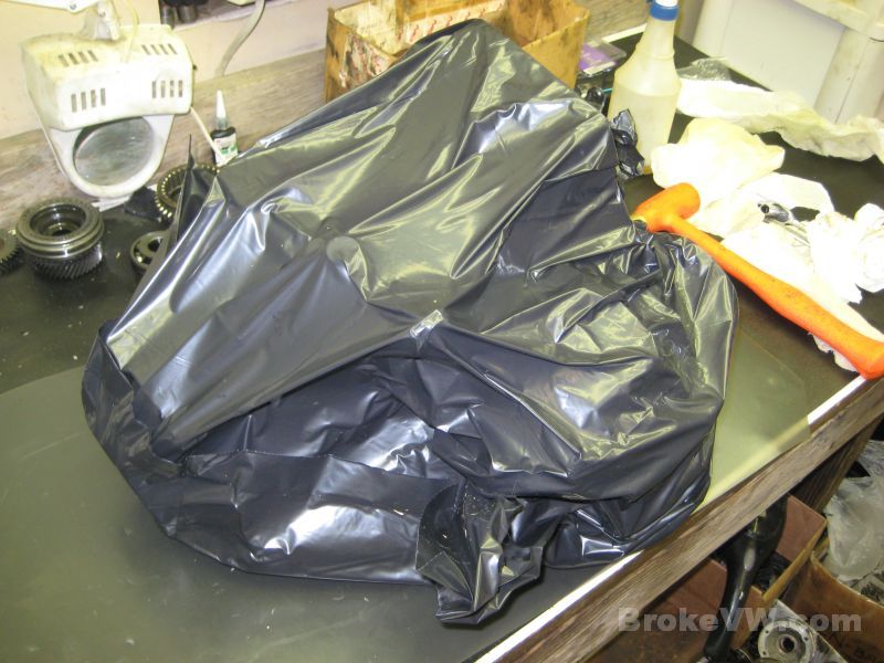
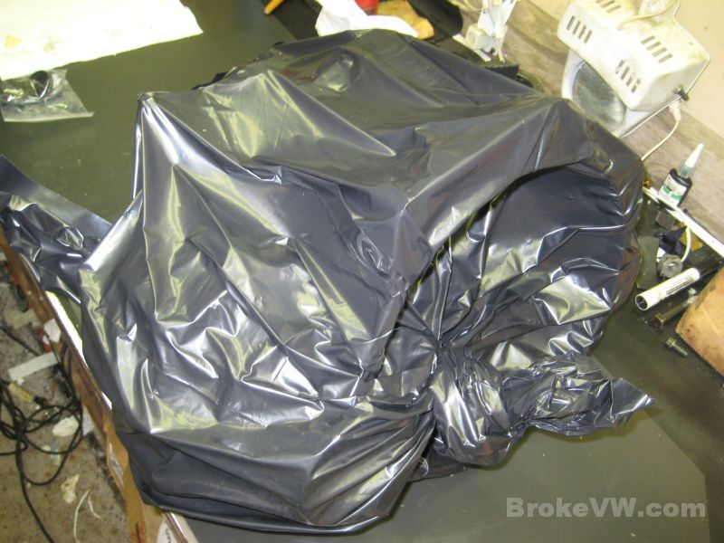
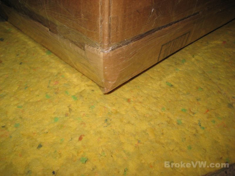
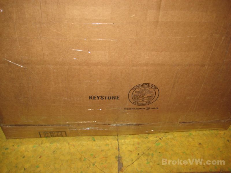
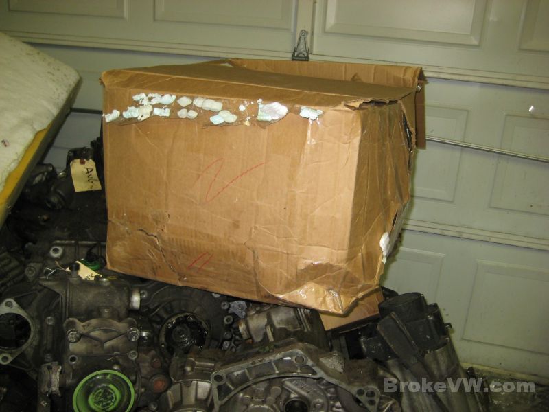
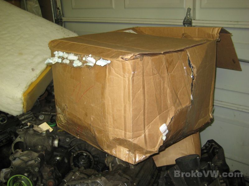
The trans as it arrived. The box was a little beat up, with a few tears and holes...
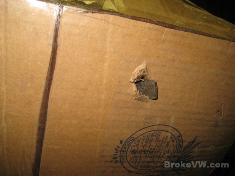
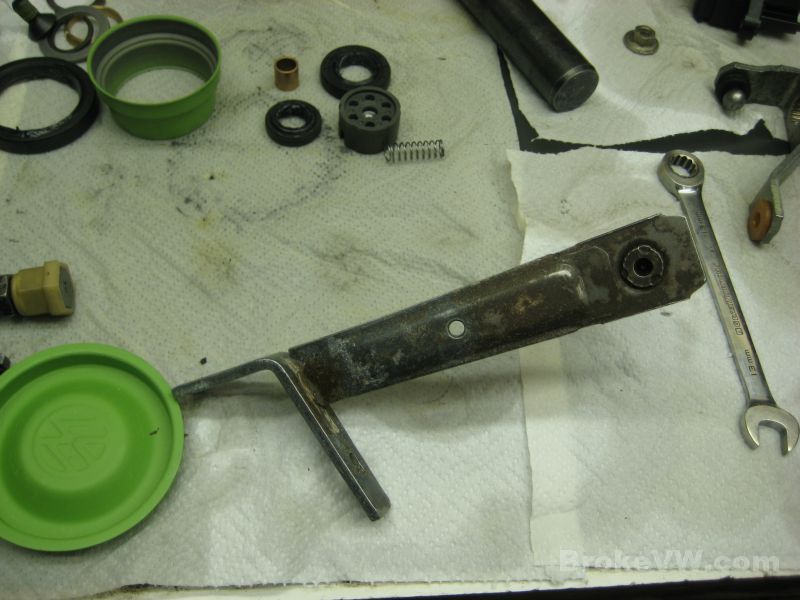
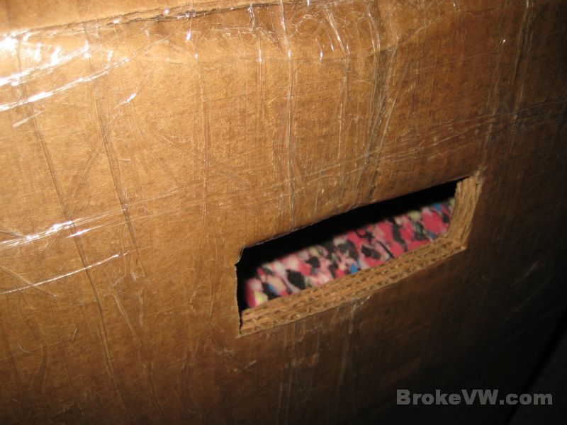
The release arm had poked through the box at some point...
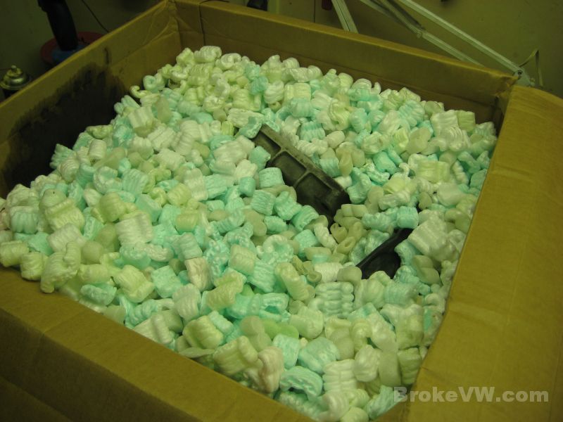
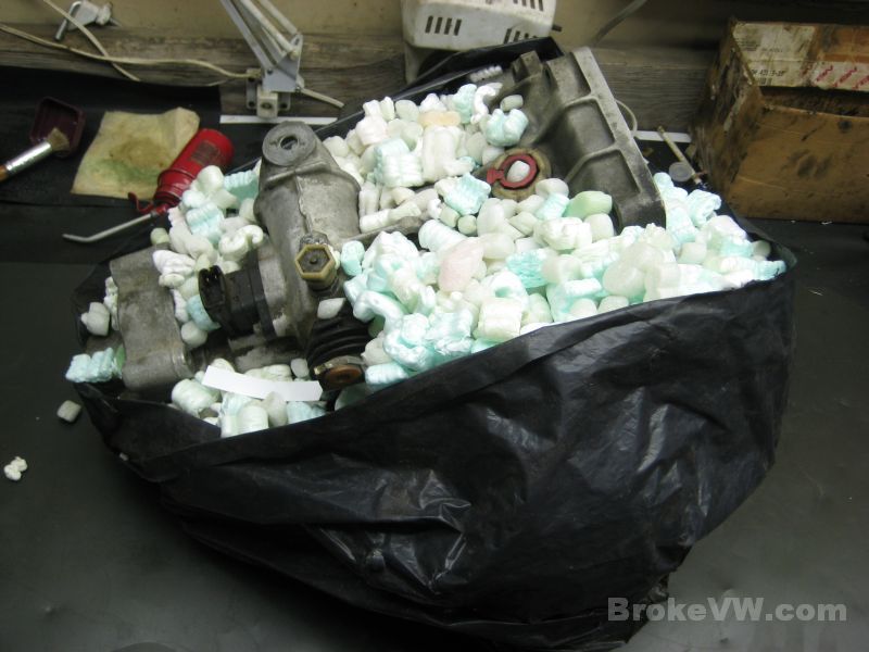
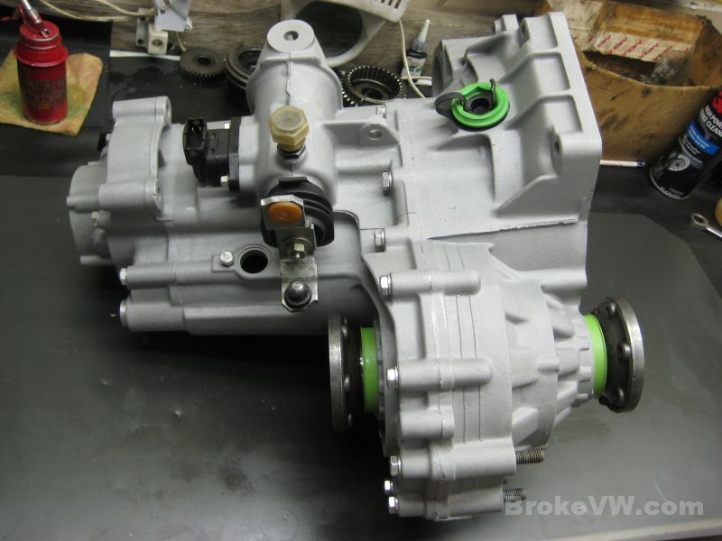
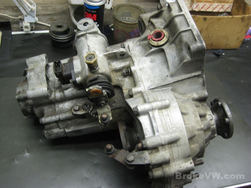
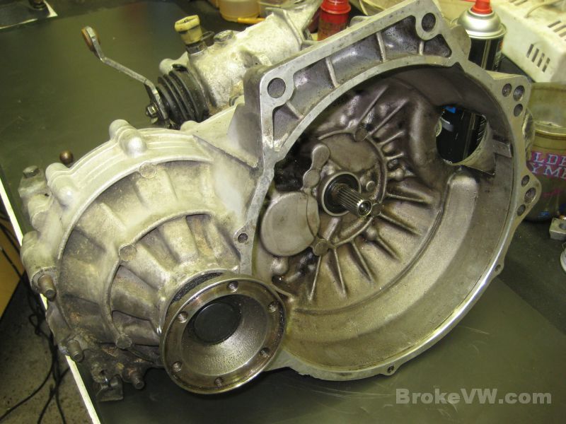
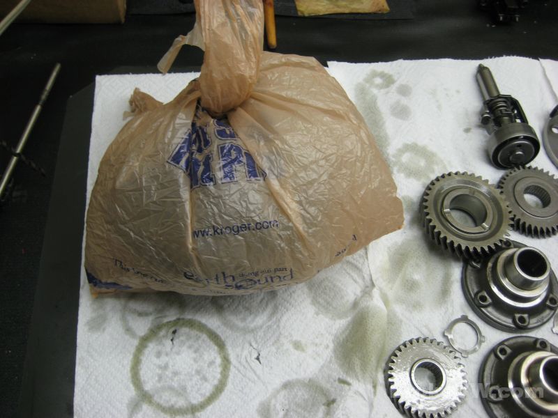
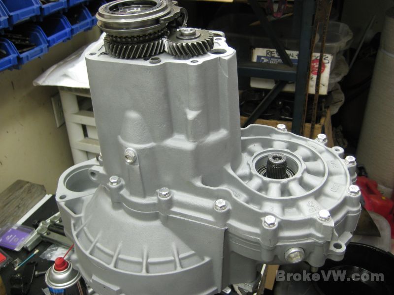
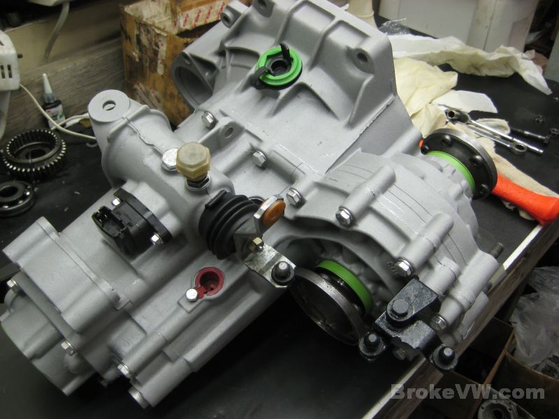
The trans after being removed from the peanuts...
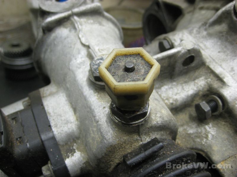
The 5th adjuster is adjusted very tightly, I'll reset that before I return it to you...
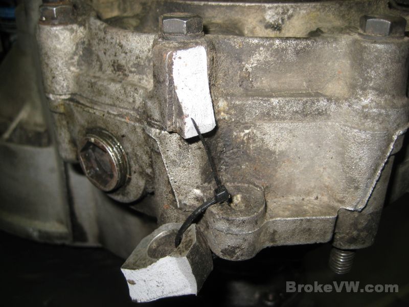
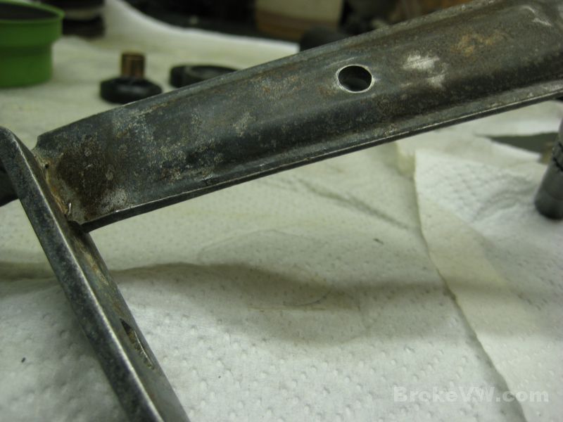
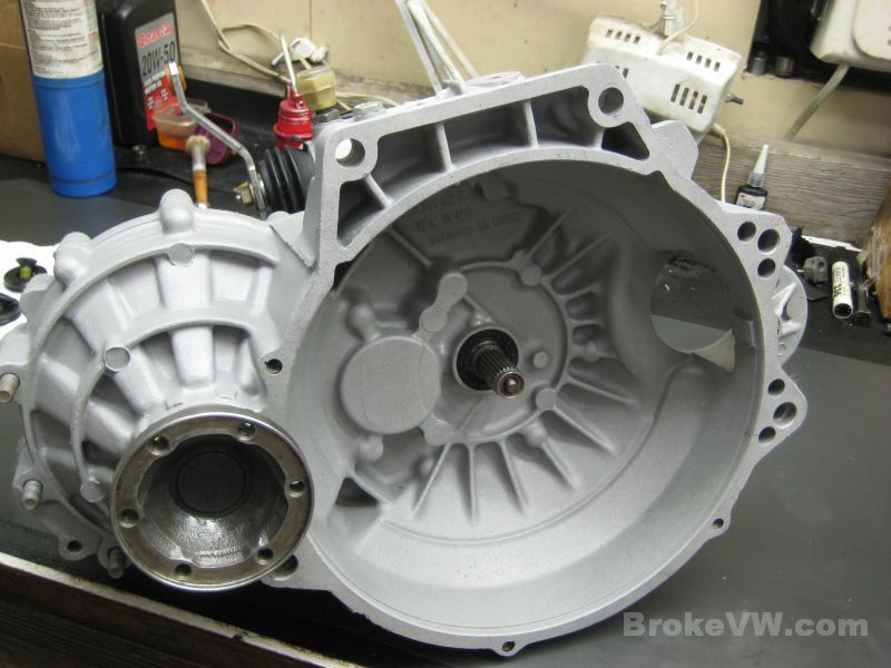
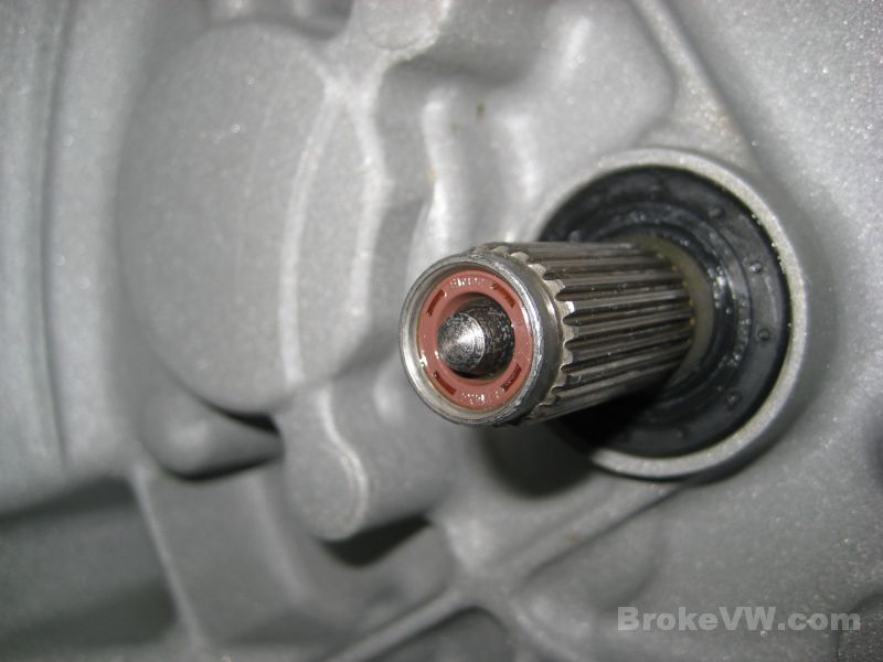
After getting the trans out of the bag, I found that the
lug has been broken off in transit, it has hit the ground pretty hard at
some point. The peanuts weren't enough to stop the trans from shifting
around inside the box, and it has been dropped onto the lug, snapping it
off.
The lug is only used with the VW special trans jack tool, so it isn't a big
deal, but it shows the kind of abuse they are put through in shipping. The
broken lug was found inside the bag at the bottom...
I'll email when I have additional pics uploaded, but for the time being the trans will be put to the side so I can carry on with the rebuilds here now.
Update 12/30/11
I was able to pick back up on your trans last night, and I began tearing it down.
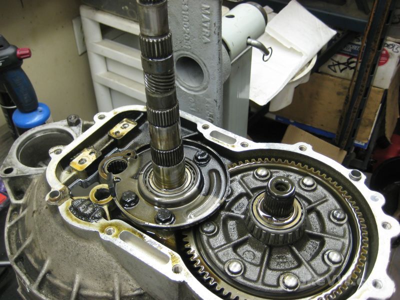
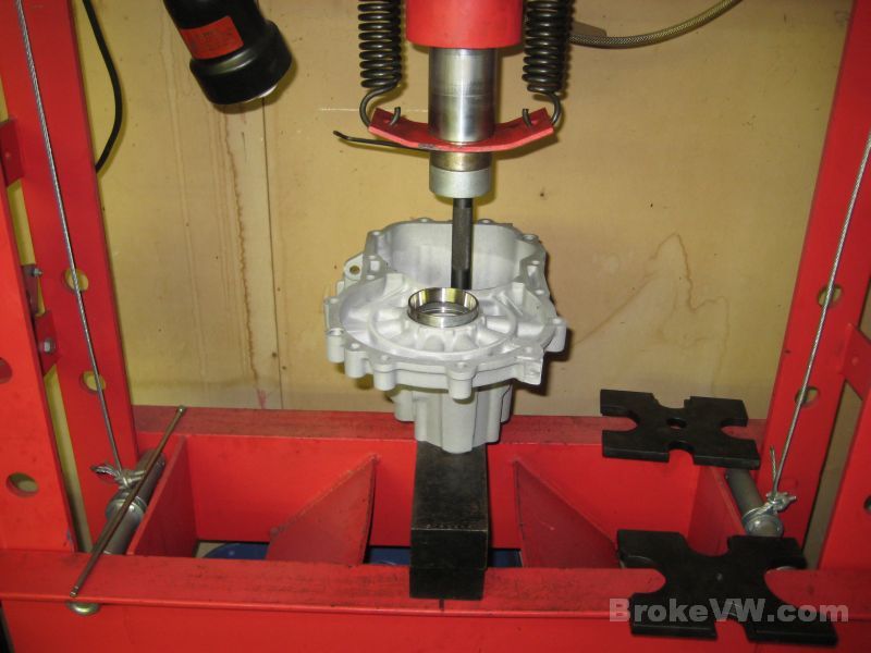
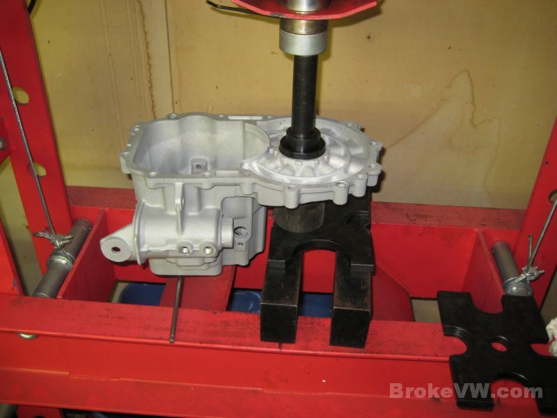
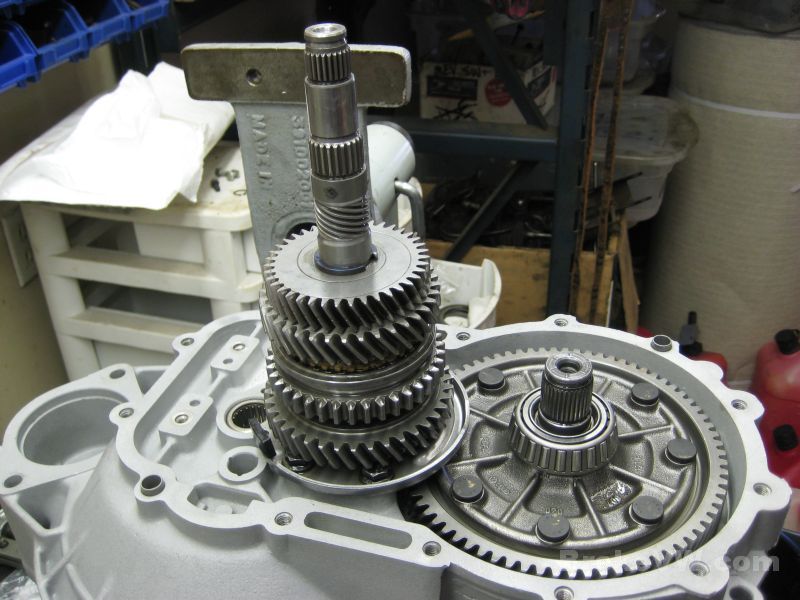
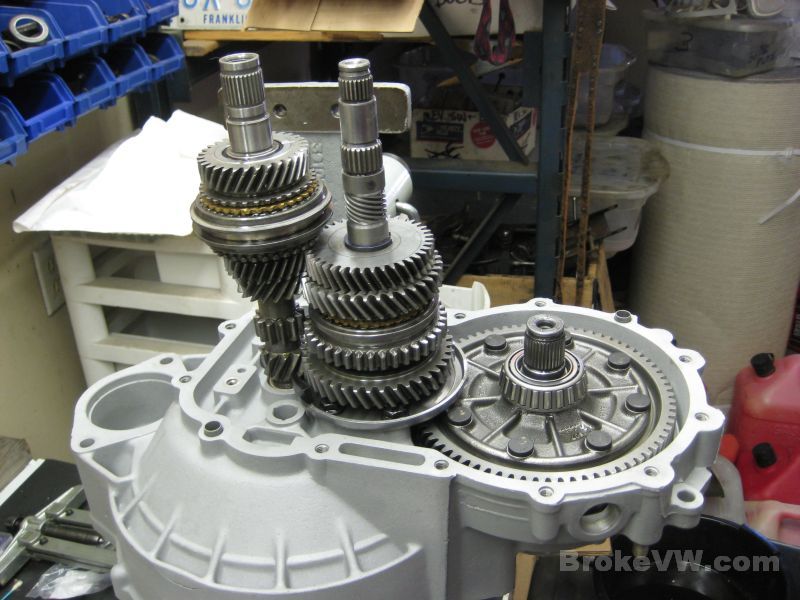
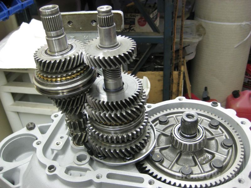
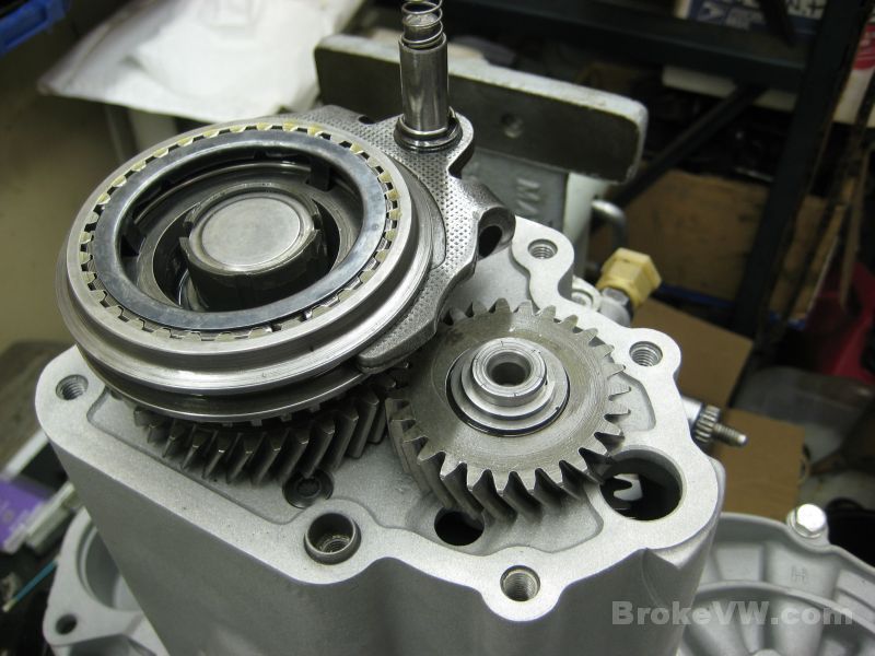
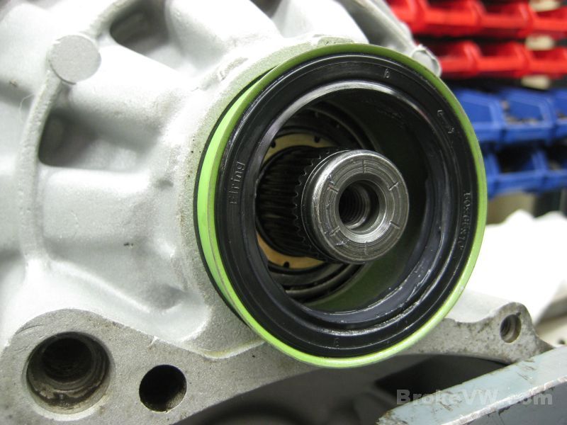
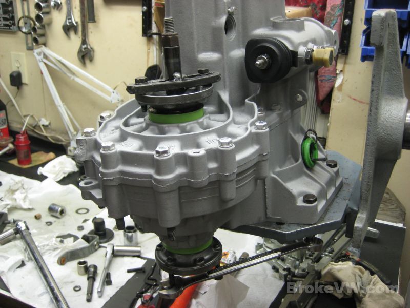
After pulling the drivers flange and the 5th gears, the casing is split and the stacks exposed...
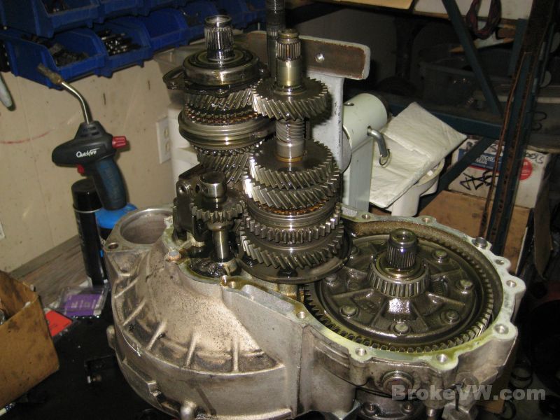
The 5th housing is not original to the trans... this is a much newer 5th housing from a late MK3 box...
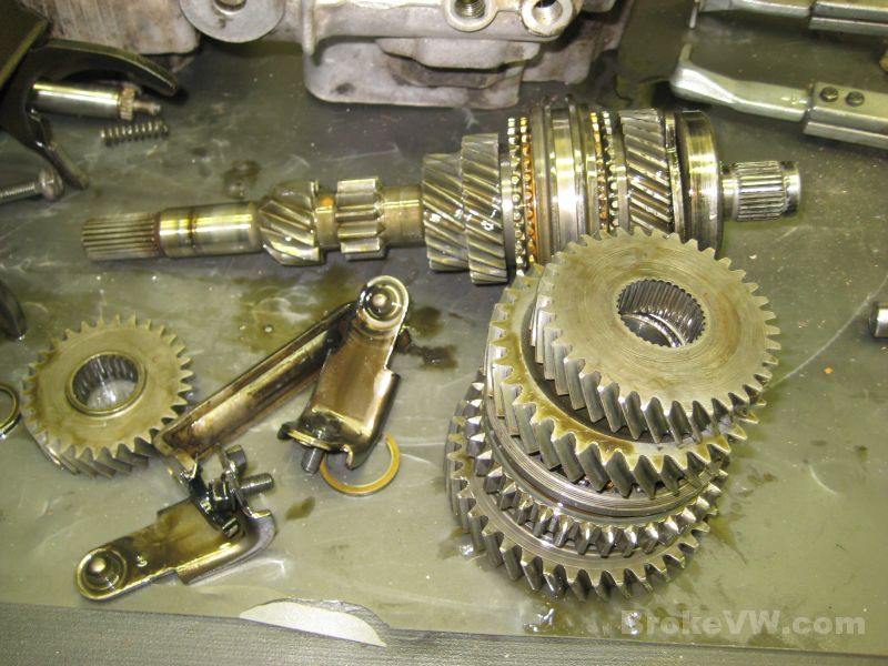
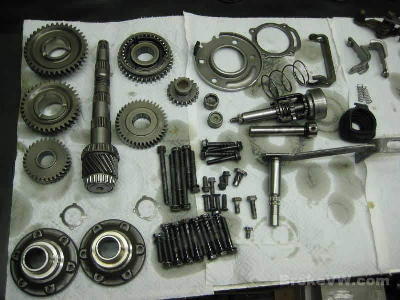
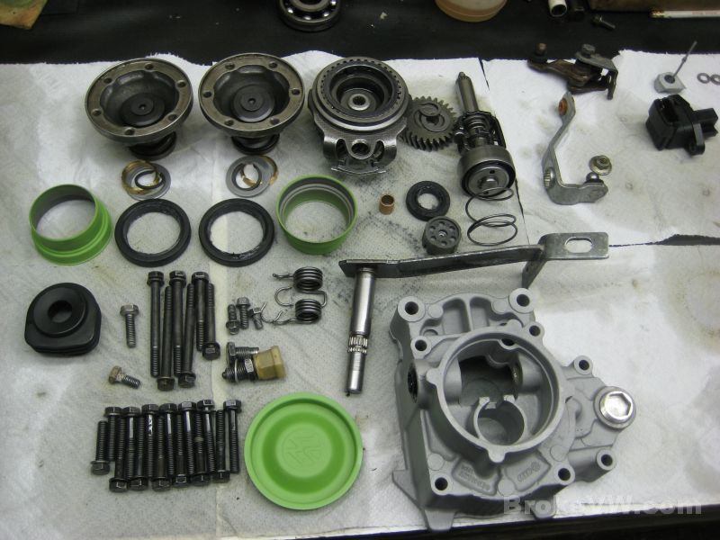
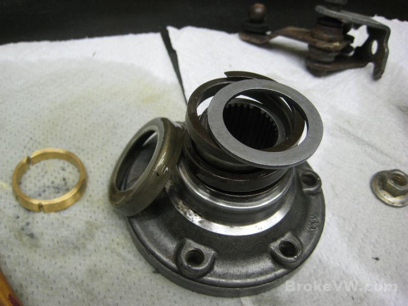
Parts removed at this point...
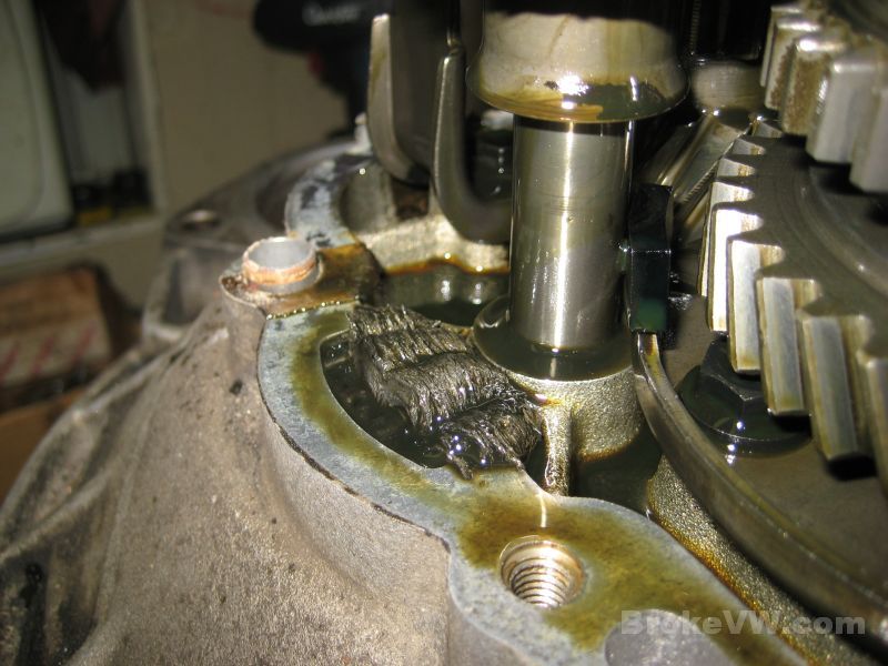
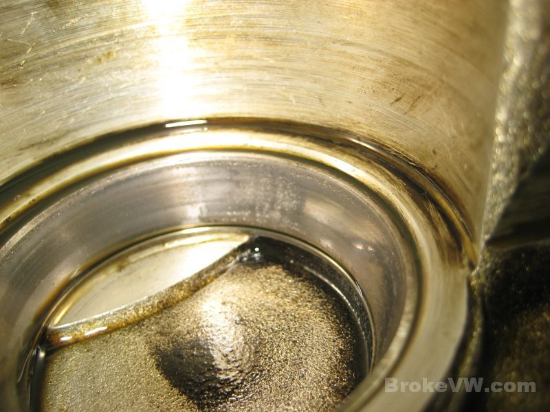
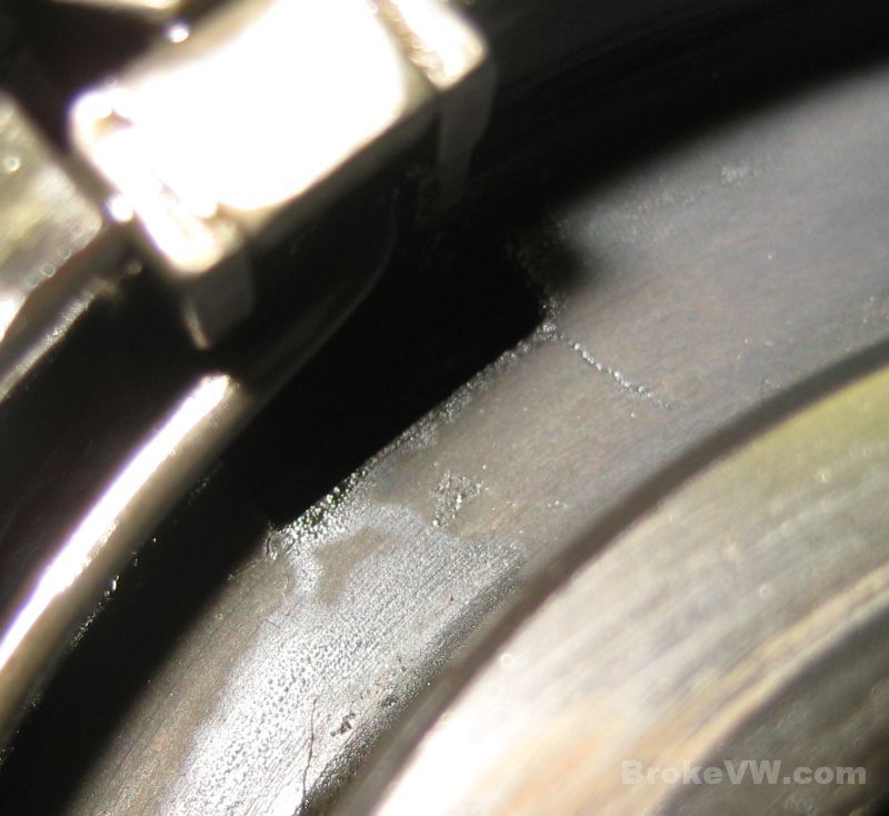
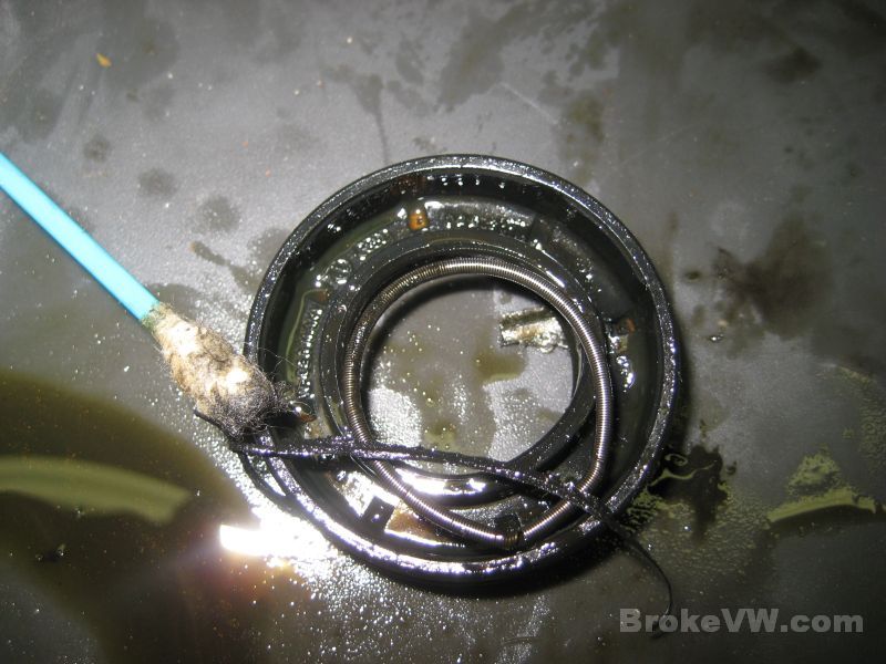
This magnet is pretty bad... they usually will have a small pile of metal on them, but this one is really stacked up, indicating something wrong in the trans somewhere...
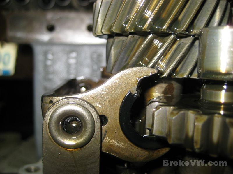
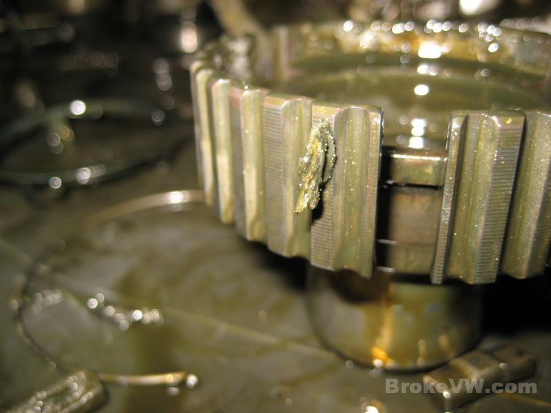
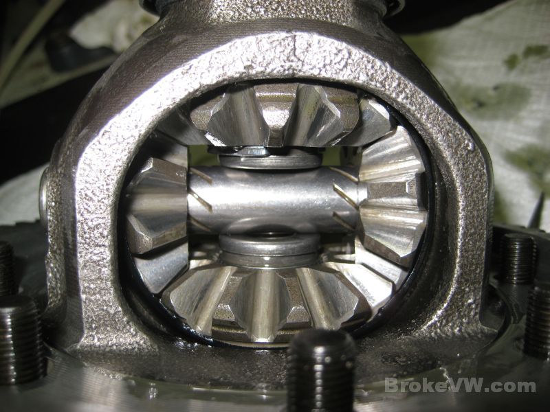
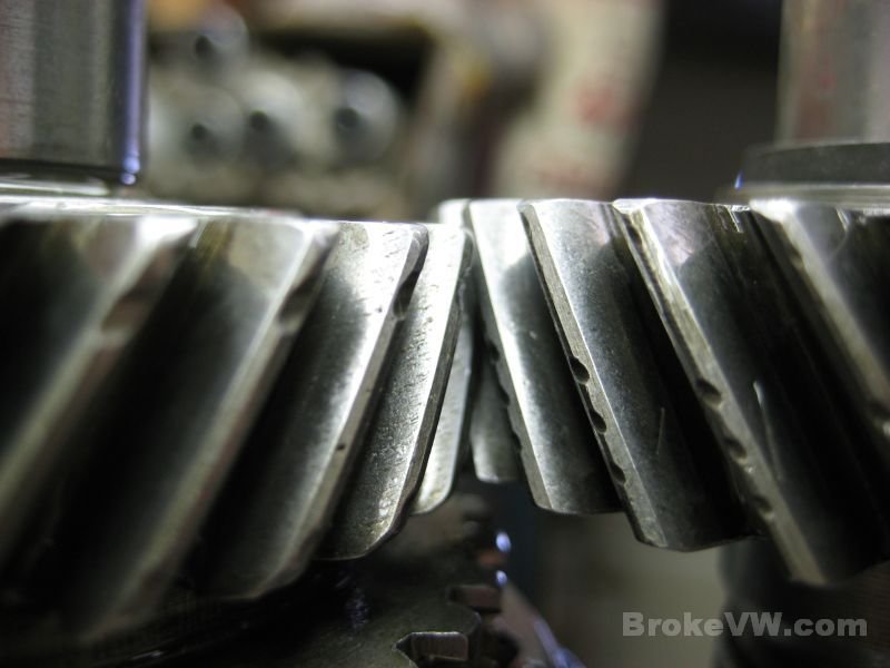
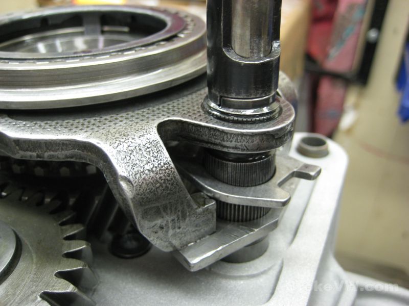
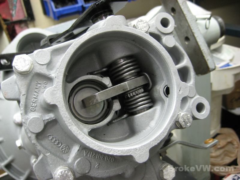
And there it is... the relay lever for the reverse gear has rubbed against the gear until it has been badly worn away. I'm not sure exactly what caused this very excessive damage and wear yet. I've actually never had one in with damage even close to this. I see them with some slight wear to the tips of the relay lever, but this one has been worn over 50% through the top of the lever. I'm not sure if it was something outside of the box like misadjusted linkage or something inside causing the parts to wear like that, but the lever will obviously need replaced...
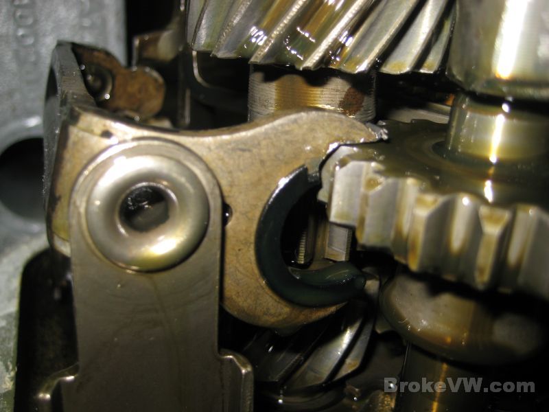
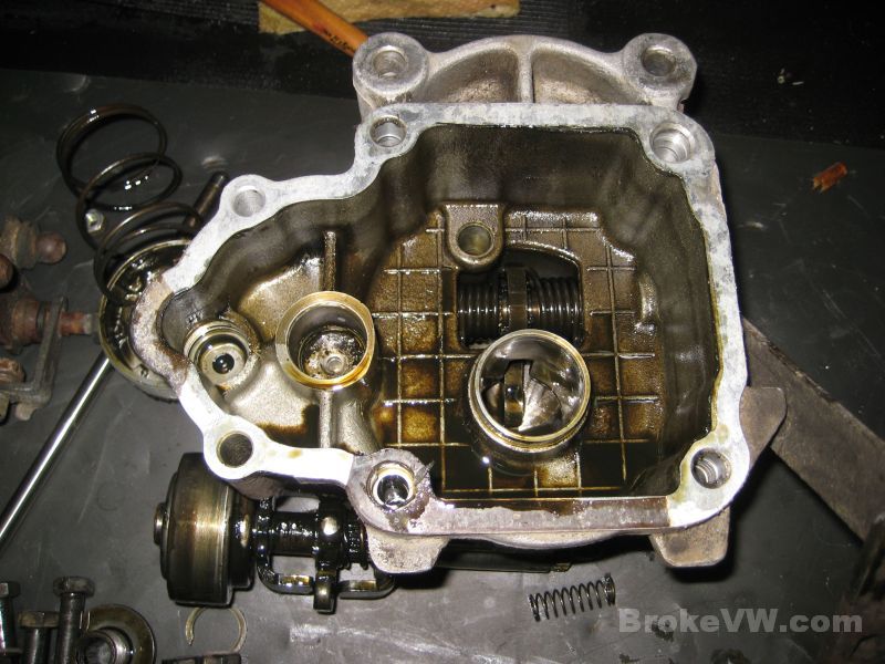
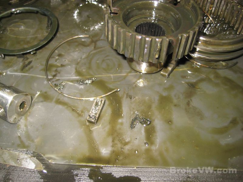
Here is a possible suspect. This is the bottom half of what used
to be a white plastic speedo gear. Someone has dropped it into the box and left
it... generally the speedo inside the box will affect reverse gear. It settles
to the bottom of the box, where the idler gear (the reverse gear in the pics
above) resides, and it will get in the way of the idler gear, not allowing it to
slide on the shaft. This could very well be the cause of the excessive damage to
the relay.
Generally people will post a thread stating the car was perfectly fine, they put
it into reverse to back out of a spot, and then it was stuck in gear. Or they
pulled in and parked, everything was working fine, they go to leave and reverse
feels solid and won't select at all. The plastic gear chunk gets in front of or
behind the idler and jams it in or out of gear.
This could very well be related to that wear... so unless I can think of another
possible or likely reason, I'm going to say the damage was due to the speedo
gear affecting the movement of the idler and relay.
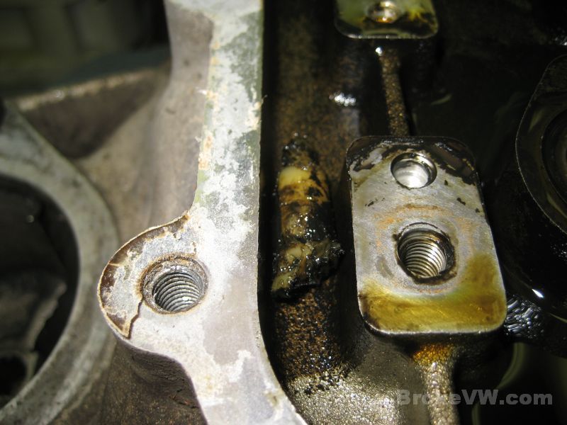
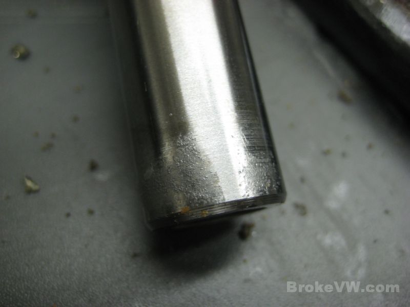
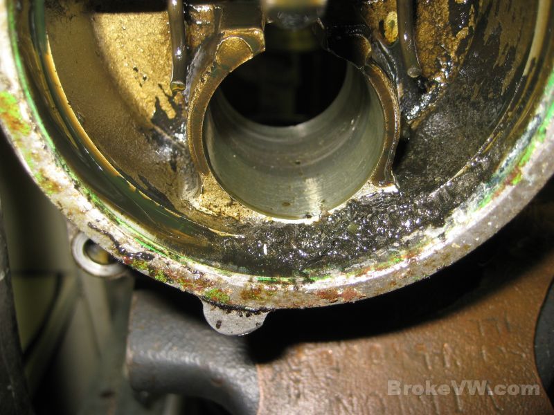
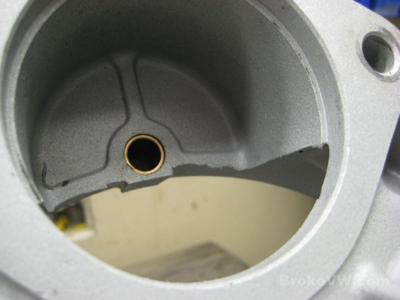
Another issue I had while taking this trans apart was the reverse idler gear shaft... it was absolutely SOLID in the trans. They usually slide out, maybe a little twist is needed as you lift it out, but they aren't too bad most of the time. Yours I had to use pliers on, a long bolt for a handle to lift with, and it took 10 mins. to get the shaft removed from the casing. I will have to replace that shaft... once it came out I could see the steel shaft had galled into the aluminum casing, welding it in place. This is something else I don't normally see, and I can't help but think it is related to the wear on the relay... if that relay was pushing on that gear long enough and with enough force to wear like it has, it could very well have done something to the shaft to cause it to gall up or stick...
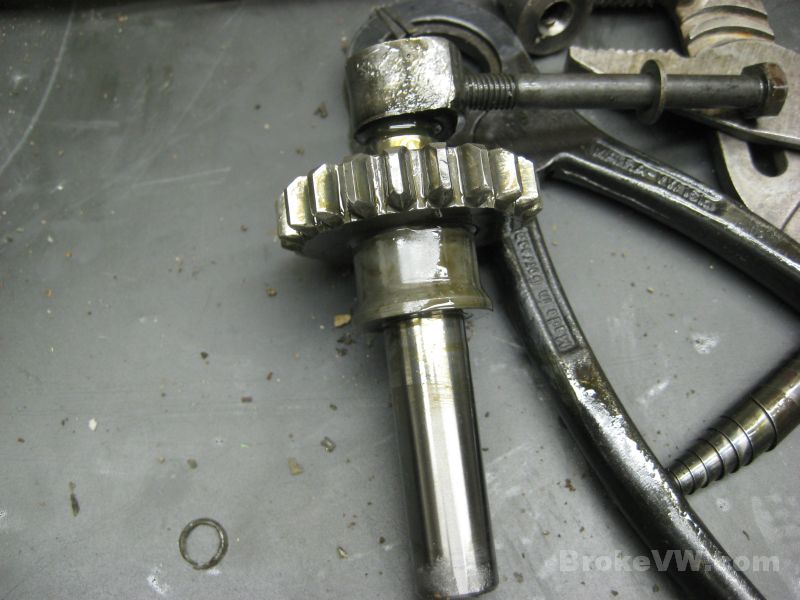
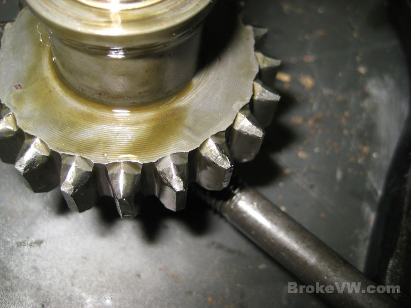
Oddly enough... the gear itself doesn't look too horrible. There are signs of light damage and wear to the teeth, but not nearly as bad as I would expect with the damage to the shaft and relay... usually the idlers are trashed, and the relays and shafts are never bad...
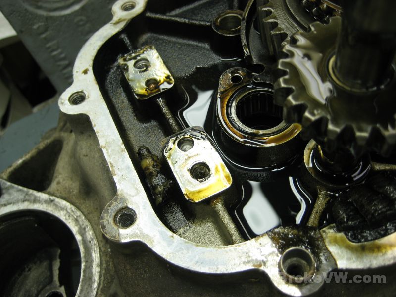
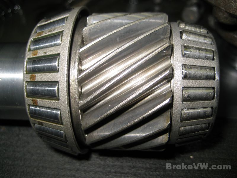
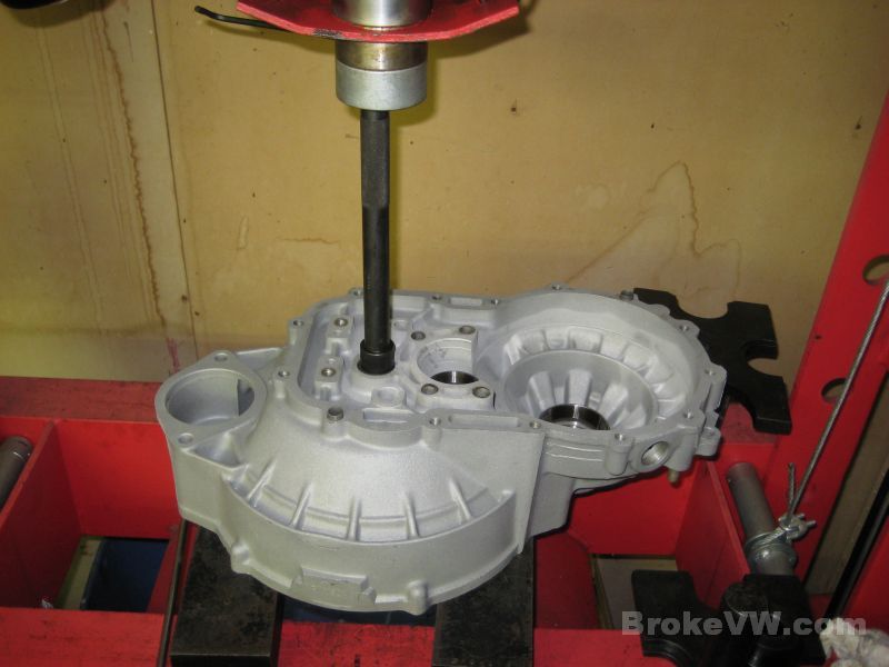
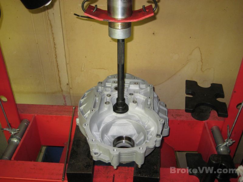
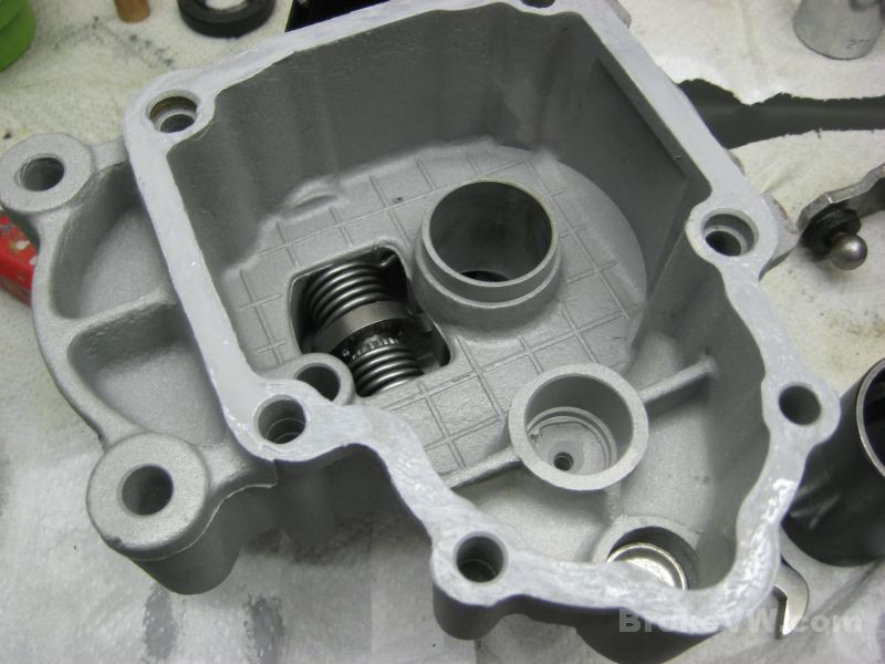
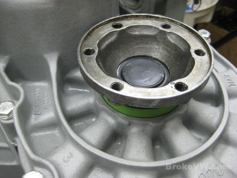
With the reverse idler shaft out of the way the trans can be stripped down to the output shaft bearing clamping plate. This is where I ran across another problem, but not one new to me. The shaft wobbled in the bearings, indicating a great deal of bearing wear, which is pretty normal. That small tapered bearing on the bottom of the shaft takes a real beating, and is usually the 1st bearing to show wear. The shaft had up/down play as well as the ability to tilt and wobble, so it was very loose. It couldn't have gotten much worse without the bearings coming apart, and when they do, the rollers get loose and kill gears so it is good these are still intact, but there was absolutely no preload on them any longer like there should be...
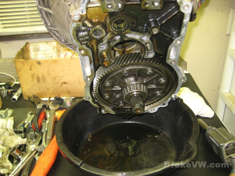
Draining the last of the oil out before I flip it over to remove the passenger flange and get the diff out...
More parts removed...
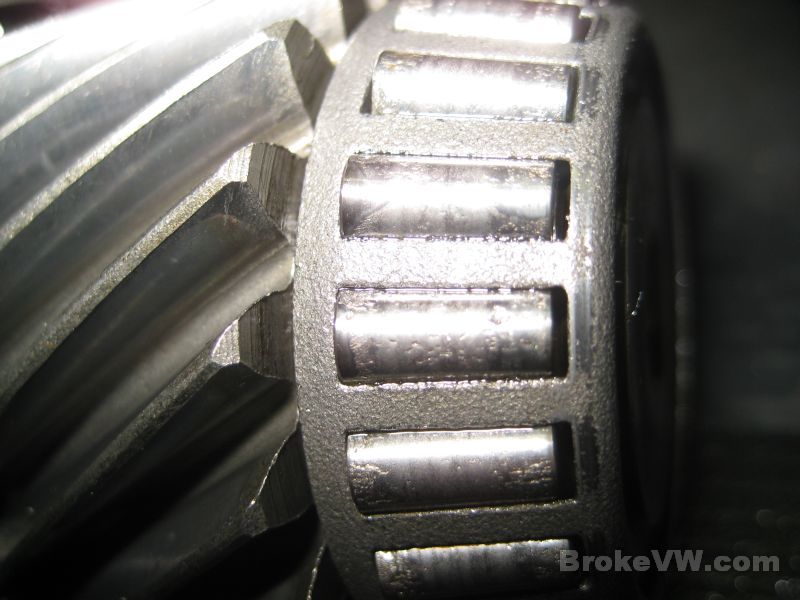
I had a quick look at the bearings and the races for the output
shaft taper bearings, the very loose ones, and they actually look pretty
good.... just very loose. They're trashed, but they aren't as bad as I expected.
I planned on seeing the rollers loose in the bottom of the bore when I lifted
the shaft out, that's how close I thought it was to failing, but the rollers
remained in the bearing, held by the cage, but it was very loose, and the
rollers were pitted and cavitated.
The bearings I stock are OEM Timken bearings, made in the US or Europe (usually
France or the UK), and they are cryo treated after I get them to increase wear
resistance and strength which is something I started doing because of the small
taper bearings always showing signs of heavy wear.
I'll carry on tearing everything down then will start cleaning it so it can be inspected. I'll email when I upload new pics to the page.
Update 12/31/11
New Years Eve and I am living it up, tearing apart a stinky 020 trans!
I have the trans stripped almost completely now, the diff is about all that is left to tear apart and it will suck because VW used some HARD rivets in the MK1 units.
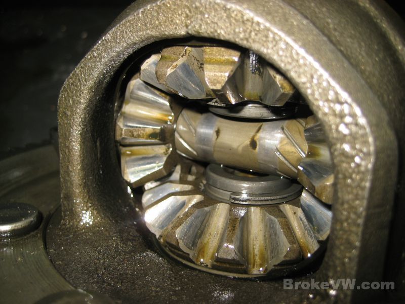
The trans actually looks pretty good inside, the bearings don't show the wear I expected, and the gears look perfectly fine. Even the diff spider gears are still in decent shape.
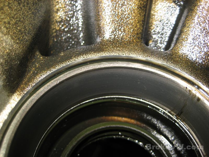
Here are some pics of the taper bearing races... this is the small output shaft bearing, it is the one with the most wear. You can see the rough pitted areas on the race along the top and bottom edges, and then a patch in one spot in the middle of the pic...
This is the large output bearing race, it looks OK. They all look worn, but this is normal long-term wear that you want to see. The pitting and rough condition of the small bearing is bad, it was on the way to failing totally and coming apart...
These next 2 are the diff taper races, again just normal wear...
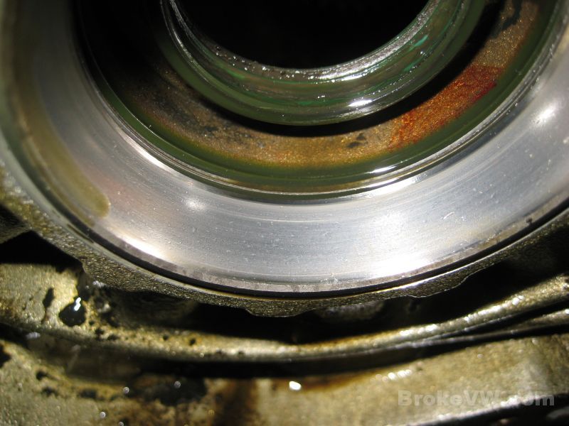
This is that bad small bearing, it is pretty rough looking, the others aren't as bad...
The teeth for the R&P set still look to be in good shape...
The diff spiders are starting to show some wear, but they aren't bad and can still be used...
Inside the gears for the needle bearing race, outside on the sync ring faces, and along the tops of the small teeth all look great....
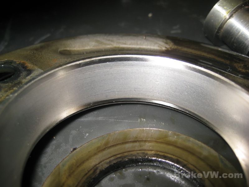
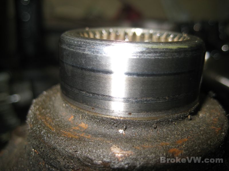
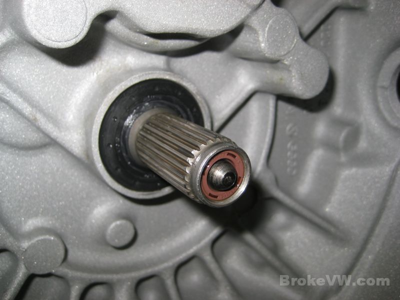
This is your axle flange. You can see wear lines from the seal lips, but they are just marked, and aren't grooved yet. Older flanges will get grooves worn into them from the seals over the years, but these are still OK to use...
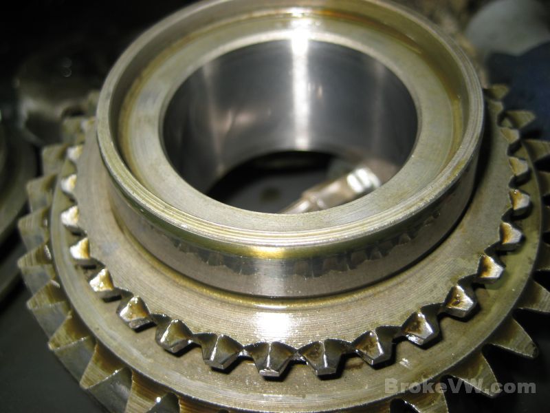
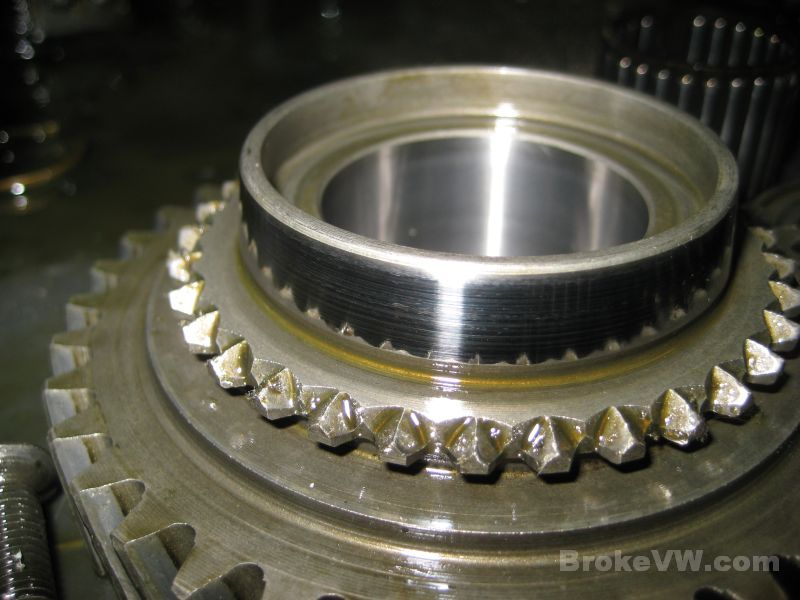
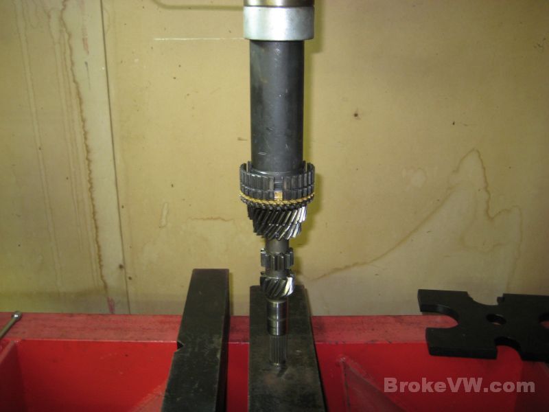
Taking apart the input shaft, I expect to find your 3rd/4th sync hub is cracked and will need replaced. It is a design fault and VW later corrected it with a re-designed hub assembly. The older units had squared notches in them for the keys, and they crack in the corners. VW changed the hub so the cut is rounded, and doesn't have corners....
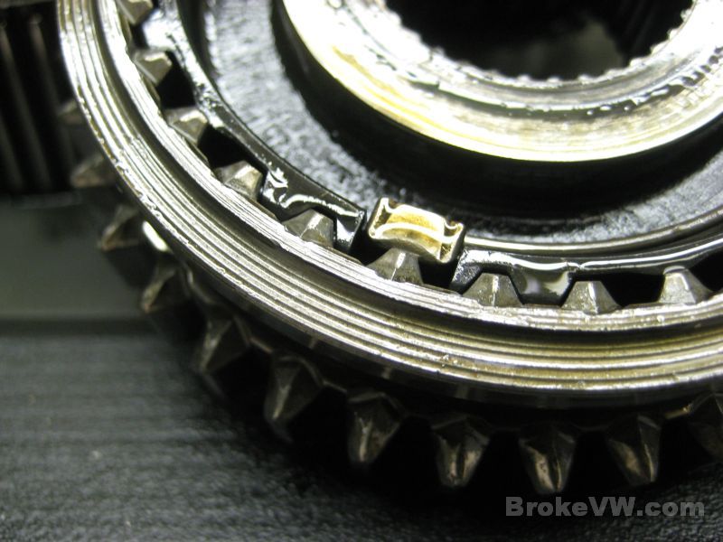
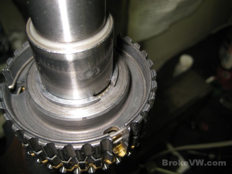
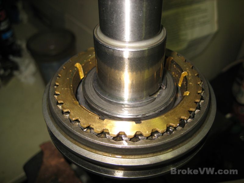
And sure enough, your hub is cracked. If you look at the squared cut behind the sync key, you can see a pair of cracks, one from each corner of the cut. The crack on the right is larger...
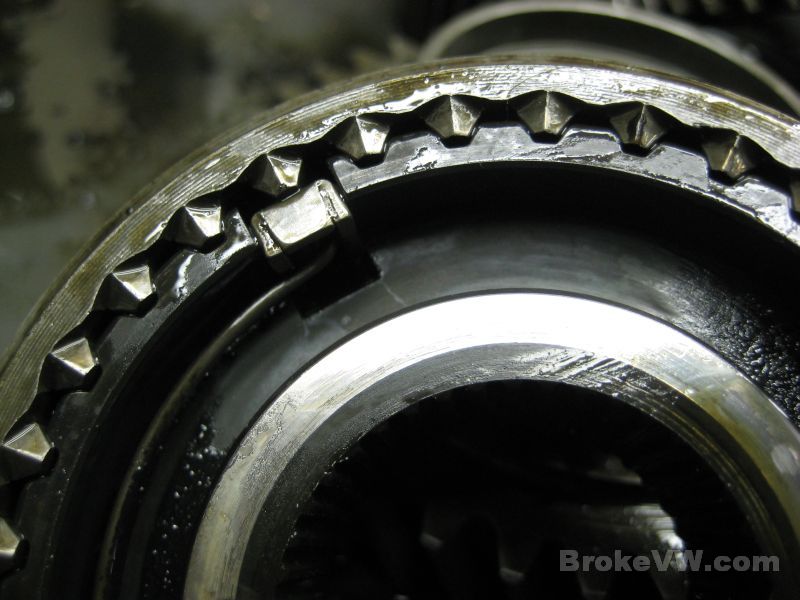
Here is a close-up of the crack on the right, the hub and sleeve will be replaced with a good used matched set from a newer trans, one that uses the updated hub assembly that won't crack...
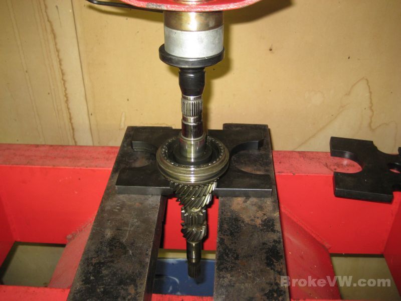
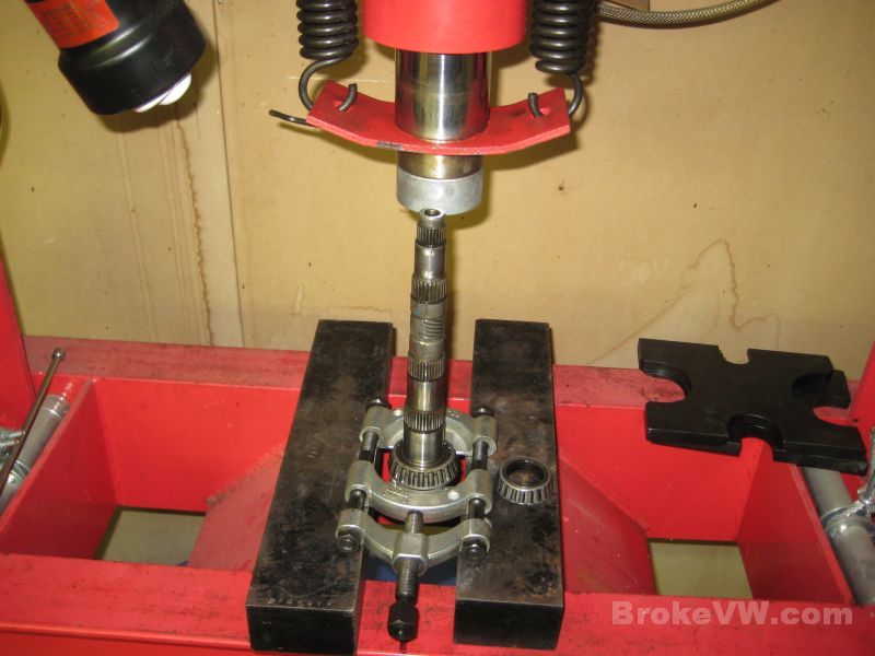
Pressing the bearings from the output shaft...
Here is more of the speedo gear. Debris in the trans tends to collect in the 5th housing, around the 5th gears. The plastic had gottne caught up in the hub and sleeve assembly of the 5th gears, and there was some in the 5th housing as well...
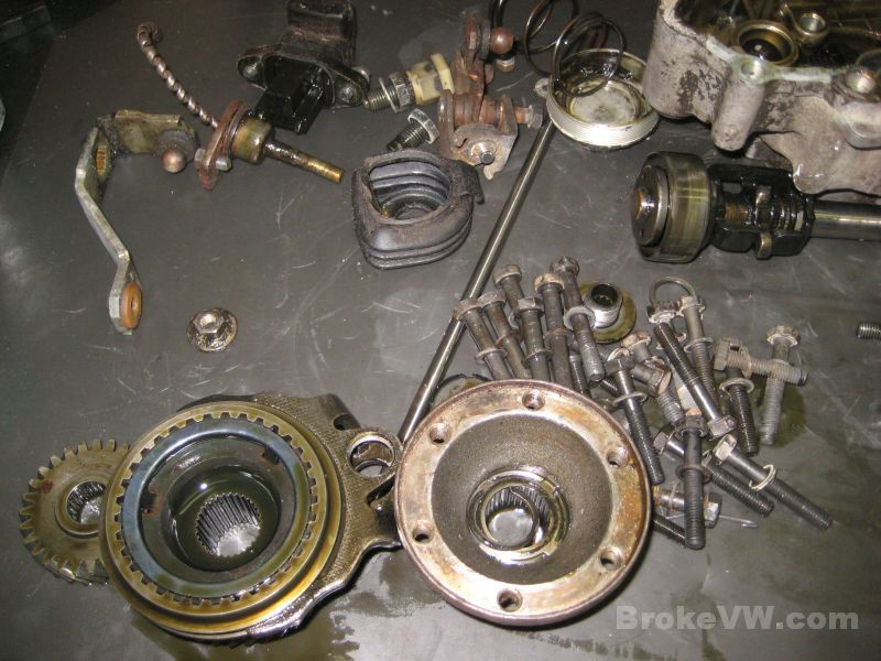
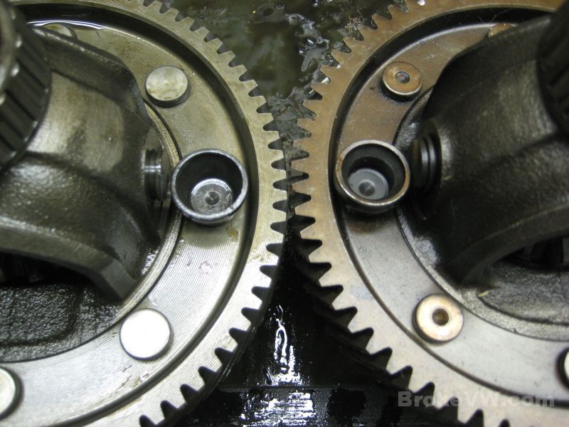
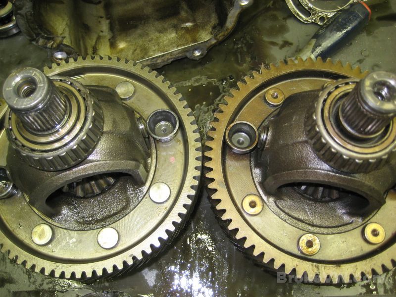
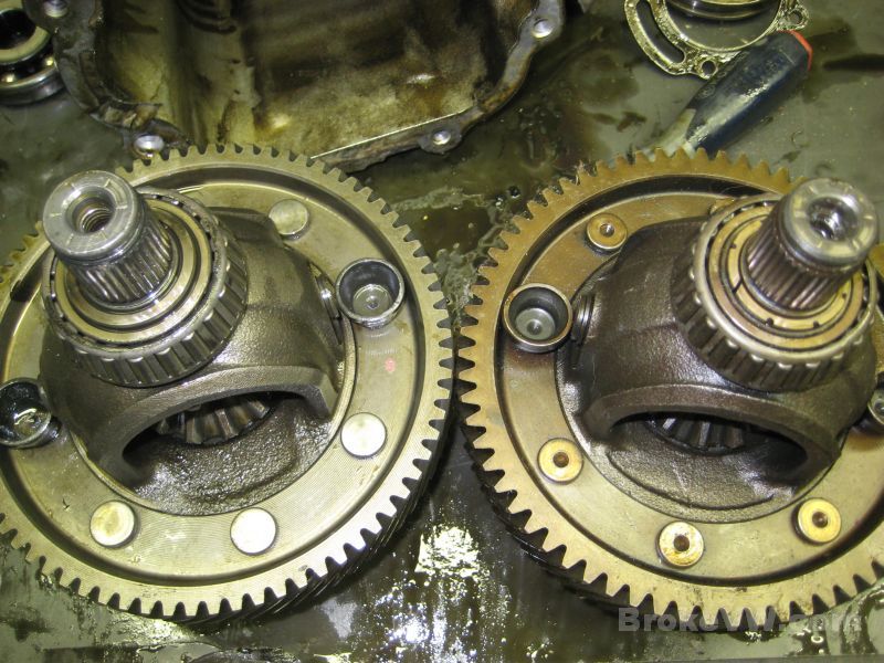
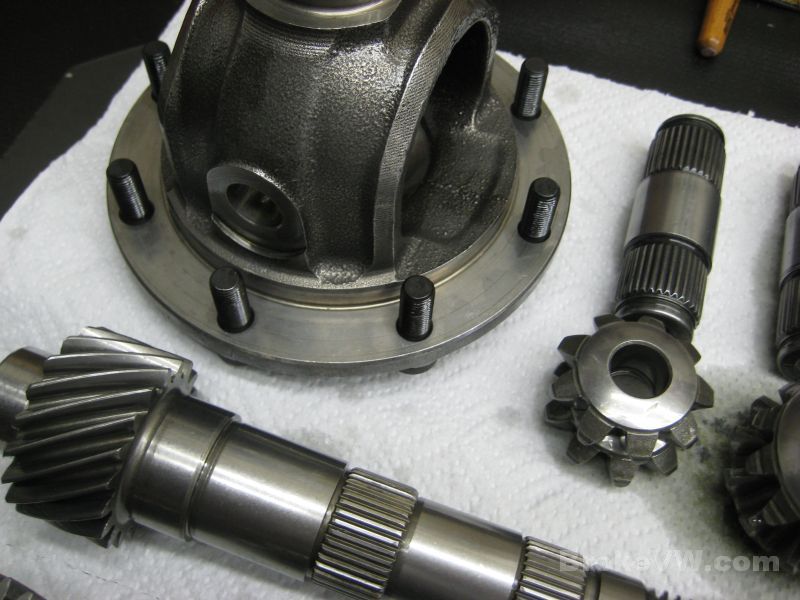
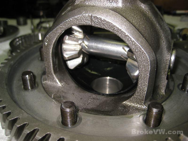
Here are a few pics, your diff is on the left, a MK2 style is on the right. The rivets on your diff will be a PITA to remove, as they are harder...
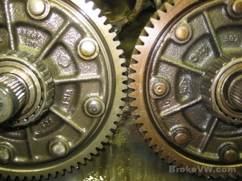
This pic shows the difference in the diff carrier, if you look around the stub axle on your diff on the left, it is solid. The one on the right has an open area around the diff stub axle. This is where the conical bronze thrust ring fits that was added to the 020 after 1983. Your trans was made just prior to this design change.
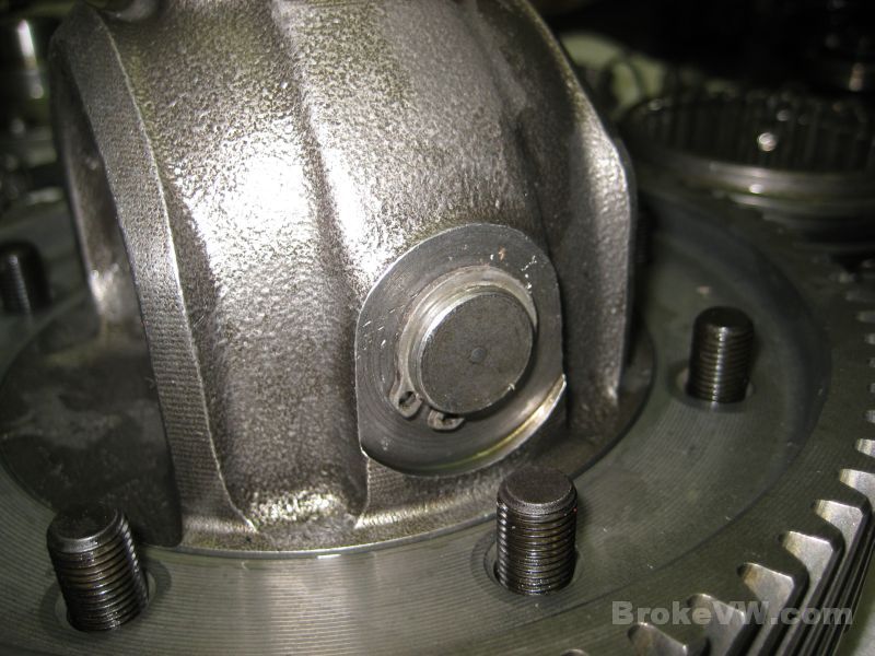
In this pic, I've installed into the diff on the right a bronze conical thrust ring to show where it fits. This is what allows the Peloquin 40% and 80% shim kits to work. The kits will not work on your diff.
The input shaft seal was an OE VW seal, but it was fairly old, considering it was marked as being made in West Germany, so it was before the Berlin Wall came down. It also had the VW logo and part number stamped INSIDE the seal, which was a new one for me...
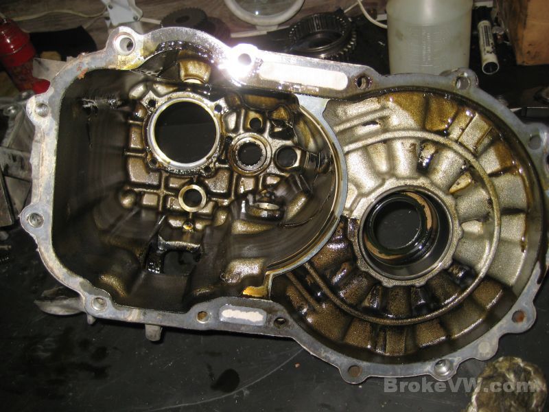
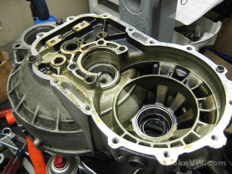
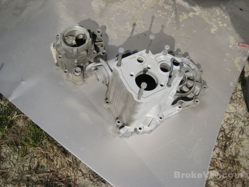
The empty case, it still needs stripped of the bearings and seals left in it...
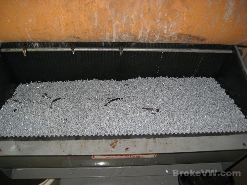
The case pieces 100% stripped down, and all of the internal parts soaking in kerosene in the parts washer...
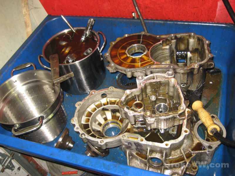
I'll let everything soak and then will put the internal parts into a vibratory cleaner, and the casing will be media blasted.
I'll email when I update the page again.
Update 01/06/11
Not much, just a few pics of the cleaning process. This pic shows the parts being cleaned in a vibratory finishing tub, and though the pic doesn't show it, the parts and media constantly roll over...
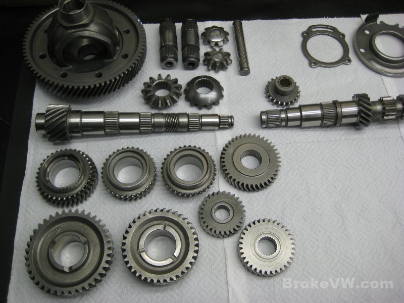
The parts come out cleaner than I could have made them by hand. These are the 1st-4th gears selected to go into your trans...
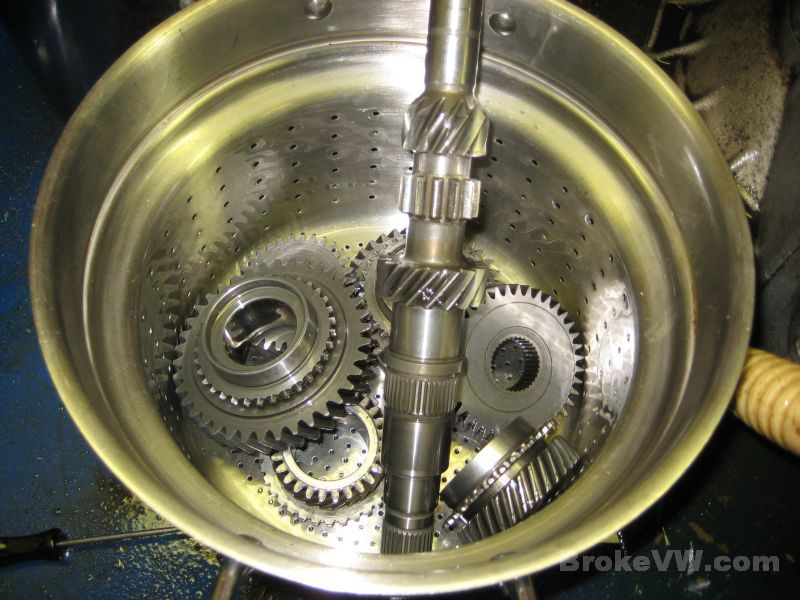
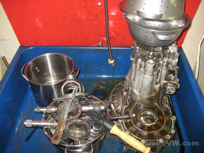
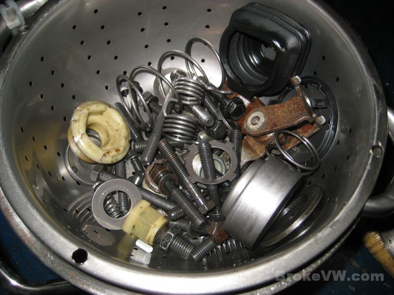
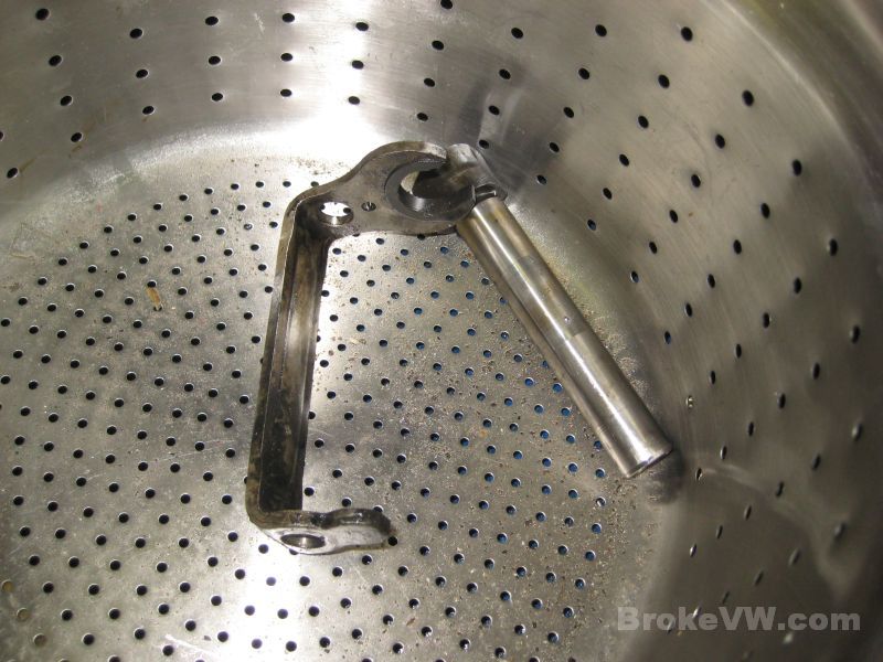
The rest of your internal parts are out of the cleaner and have been rinsed in kerosene in the parts washer. The case needs wiped off, then it will be media blasted to clean it fully. The double-strainer is used to clean the small parts like bolts and so on. They are put into the strainer, the top and bottom strainers are bolted together to form a ball, and it is filled with the vibratory media and put into the machine to tumble around...
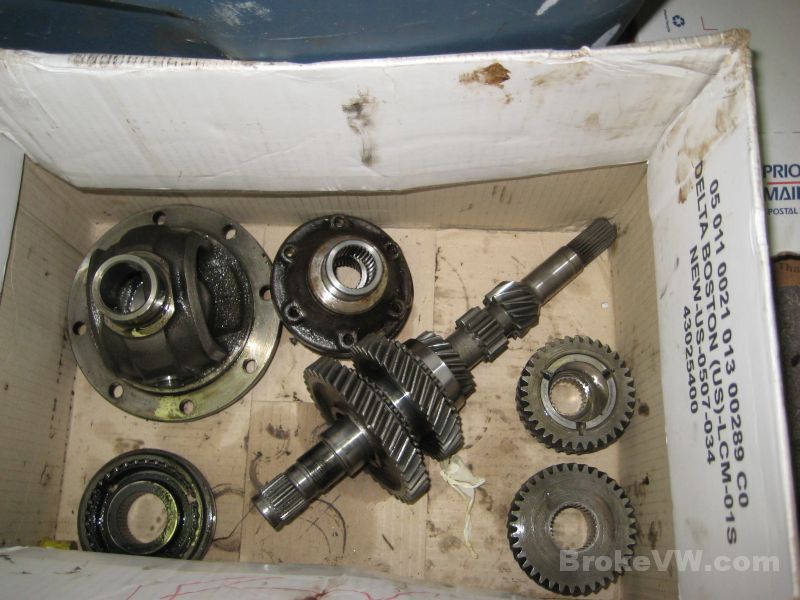
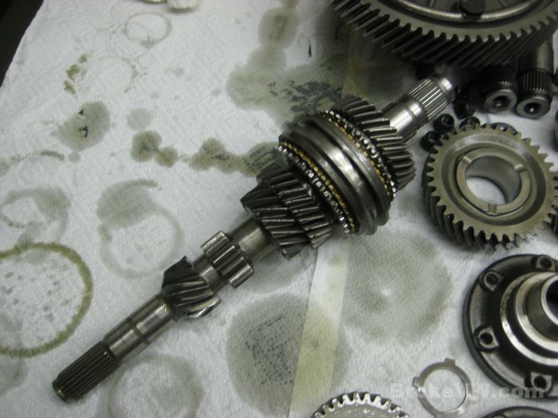
Here are the used parts out of your trans. The input shaft and 1st and 2nd gears, the old diff carrier, the old 90mm flanges, 3rd and 4th gear sets, and the cracked 3rd/4th hub assembly...
The internal parts will sit to allow the kerosene to run off then they will all be rinsed, dried, and oiled. Once oiled they are bagged up and put to the side until needed for the build.
The casing will be allowed to dry in the parts washer after a rough cleaning, then it will be prepared for media blasting by filling all the threaded holes with bolts and installing old bearings and races into the bores.
Update 02/01/12
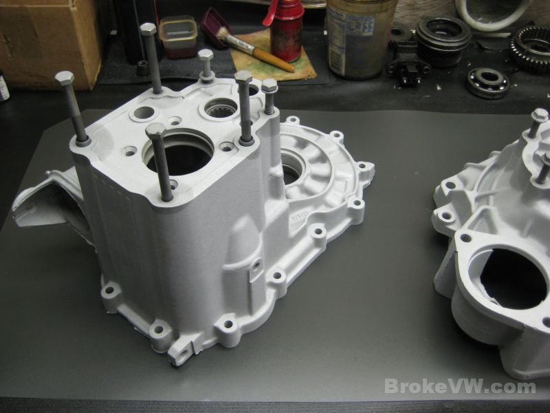
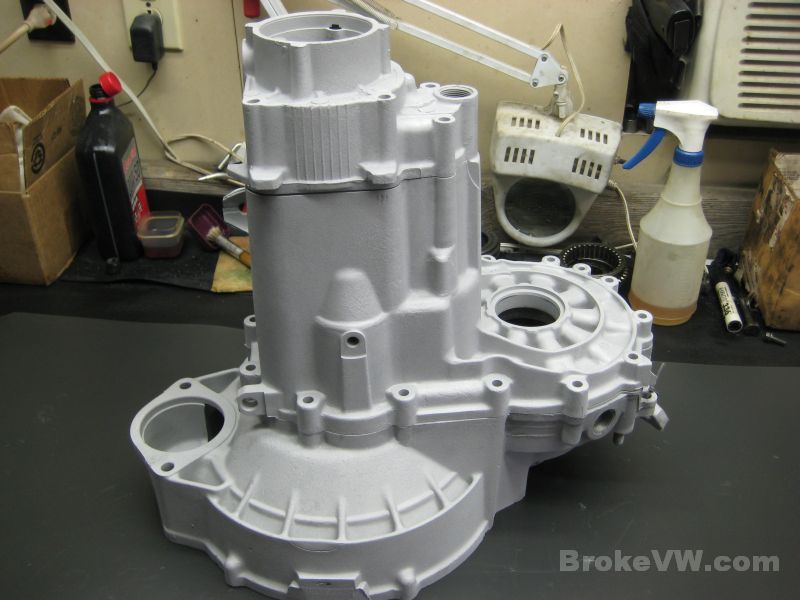
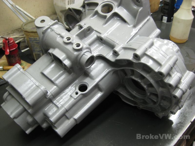
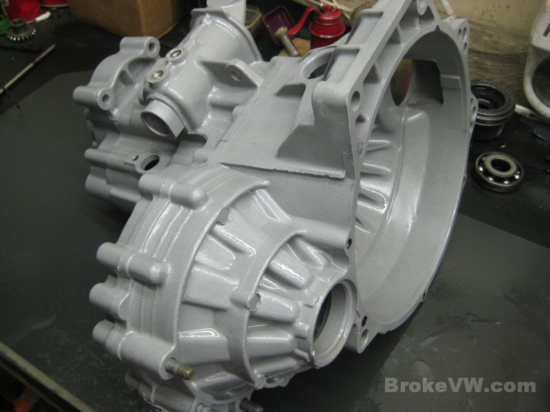
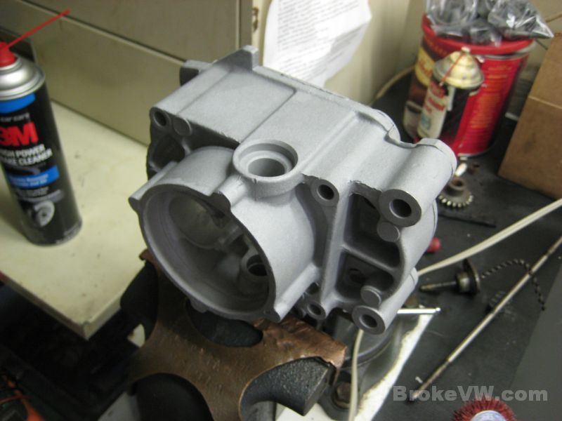
The casing has been blasted with both sand and glass bead, and has turned out pretty well.
Here the casing is being blasted and you can see the difference in the 2nd pic between the original areas and the blasted areas...
Once blasted, the bolts and old bearings are removed...
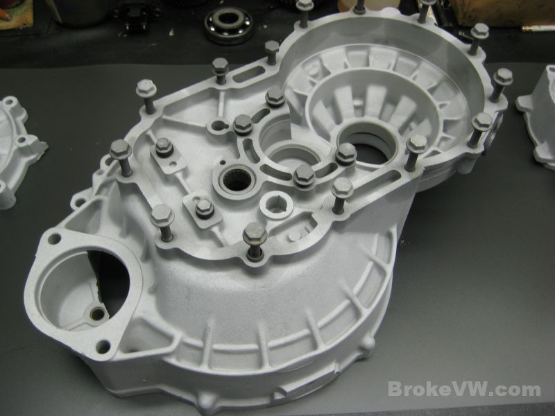
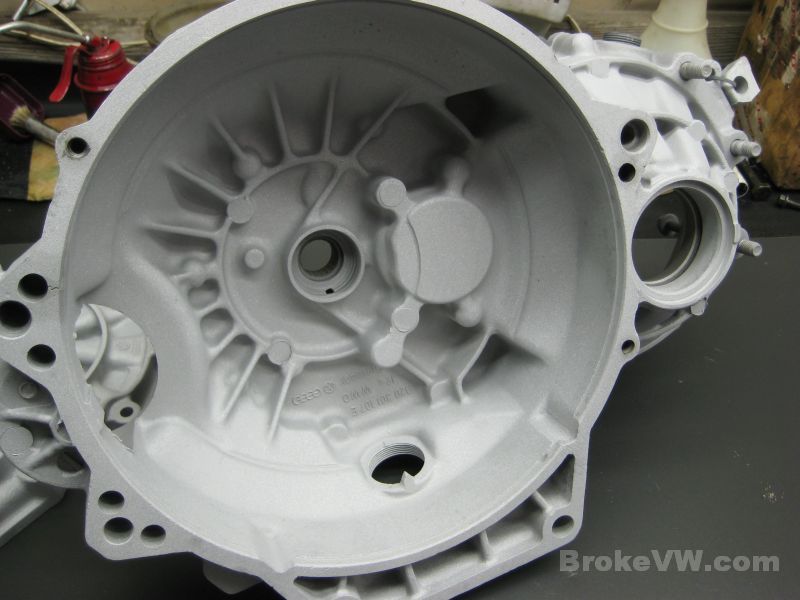
Here is how it turned out... it still needs rinsed several times and dried, but once it is totally sand-free I can start on getting the internal parts out of the parts washer, get those rinsed, and then start on the build...
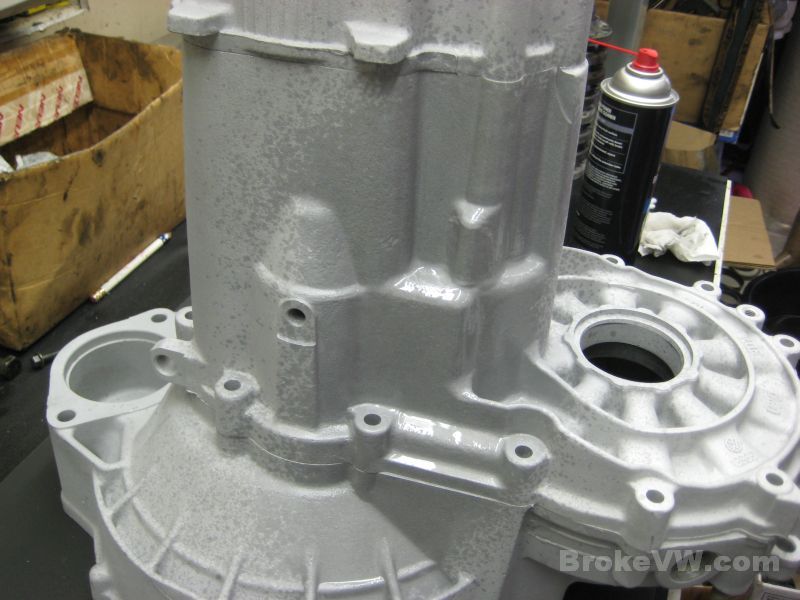
The case has been rinsed and dried, then it gets sprayed with WD-40. The WD-40 allows me to handle it during the build without making it dirty form any grease or grime that might be on my hands when I touch it. The WD-40 holds it in suspension, preventing it from getting into the porous aluminum surface and staining it. You just wipe it away with a clean towel and re-apply more WD-40 to the case....
Next will be getting the internal parts rinsed, dried, and oiled.
Update 02/16/12
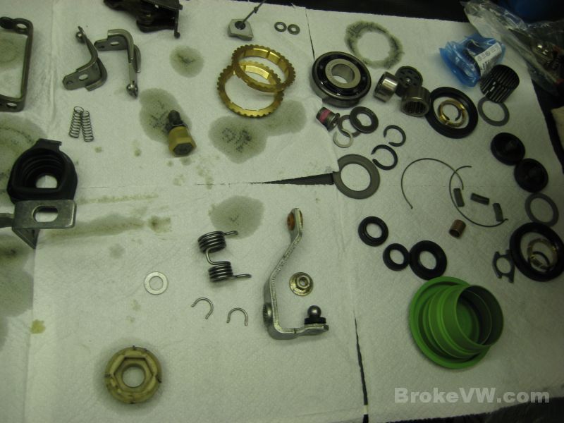
The parts are cleaned and ready to start being built.
The first of the parts are dried and lined up...
A few parts not rinsed yet...
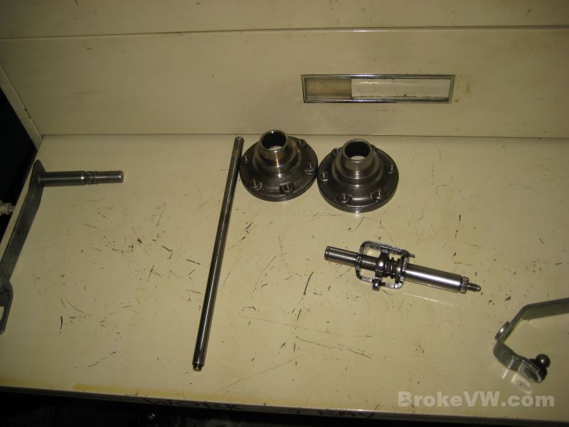
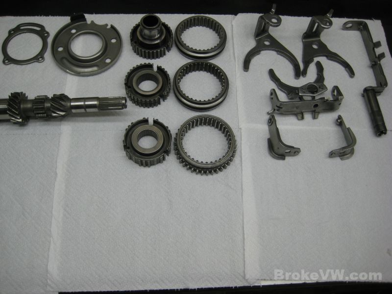
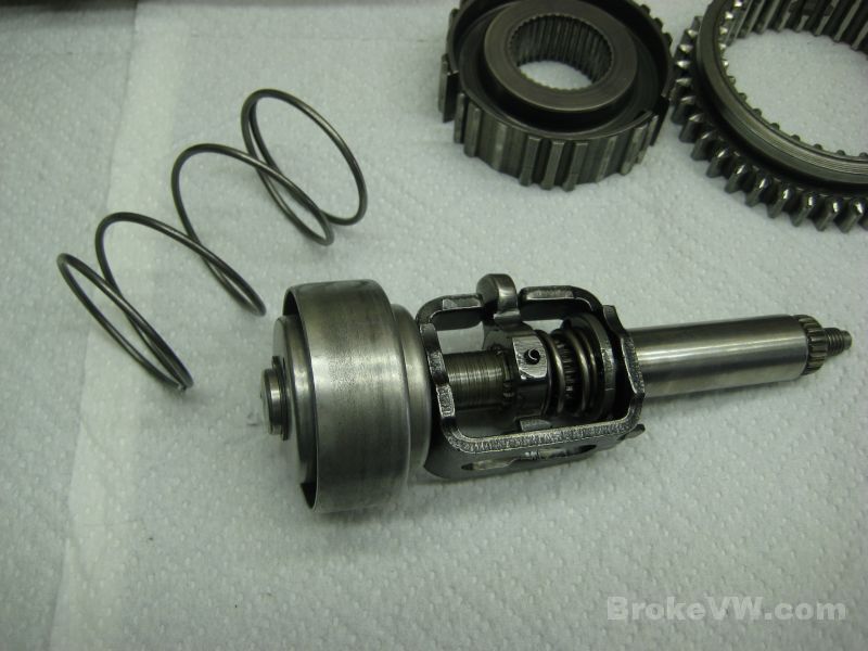
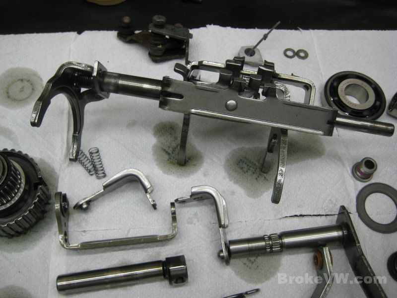
With the parts now rinsed and dried, I assembled the selector assembly...
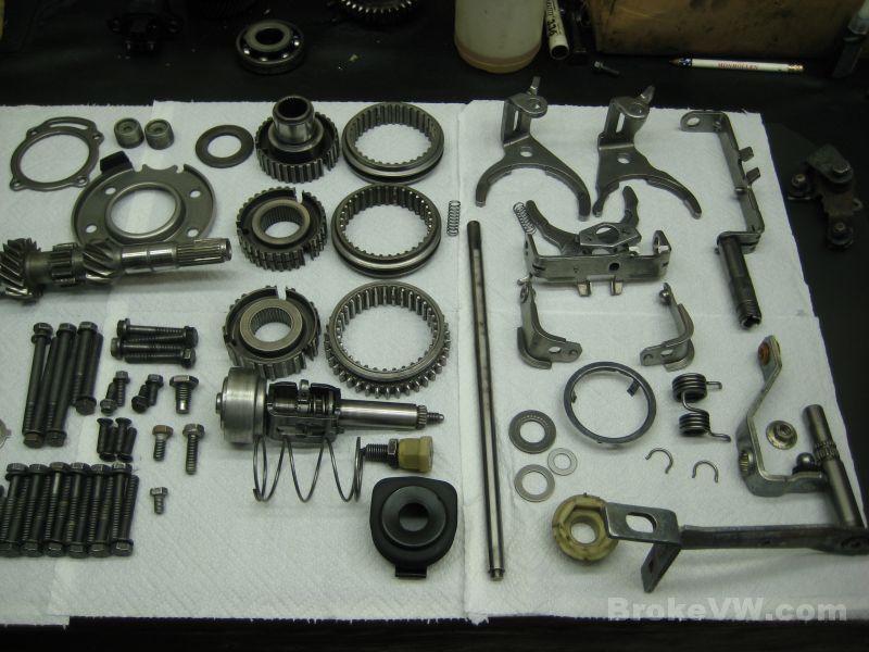
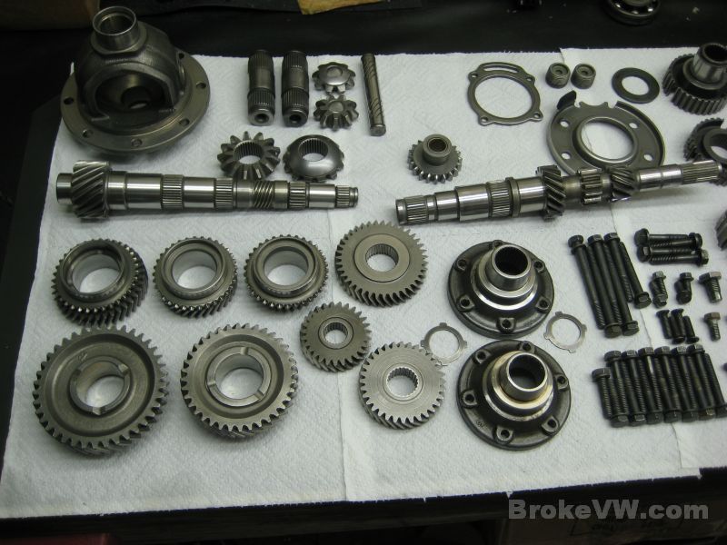
All of the parts are laid out and ready, not including the ring gear which is not shown, as it was to the side to be heated for install onto the diff...
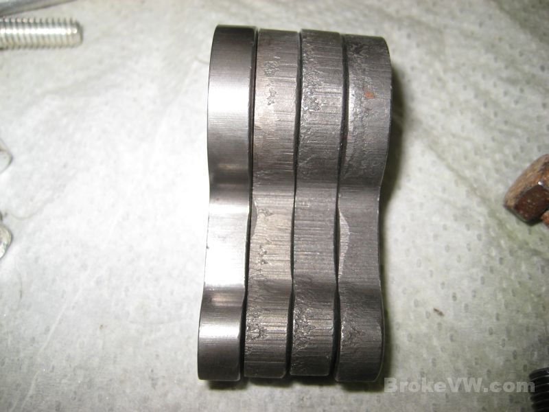
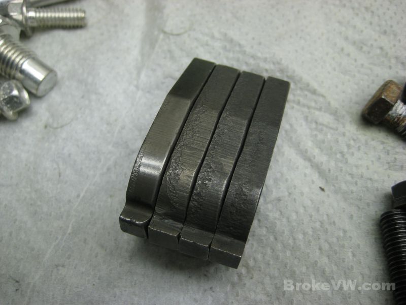
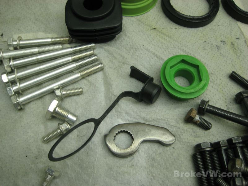
A replacement reverse relay lever and idler gear shaft...
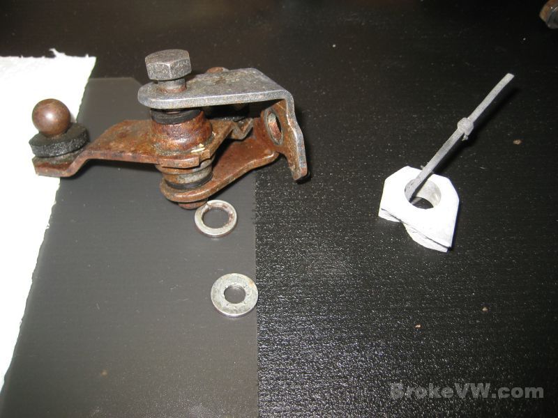
The linkage piece and the broken chunk of the case found in the box when it arrived here. I blasted the broken piece of casing, so it can be TIG welded back on later if you want. I don't have a TIG here or I would stick it back on, so I'll send it back with the trans and if you know someone who has one, have them weld it back on if you like. It is only for the special VW trans jack tool, so most people never use it...
The new parts laid out. From left to right, top to bottom there are the 4 Timken taper bearings, 5 gear needle bearings, the input shaft ball bearing, 2 shaft roller bearings, the TO bearing, 2 green sleeves, a green end cap, the ARP bolt kit, a 5th bolt, thrust washer, circlip kit, sync keys and springs, shaft seal set, under the red ELRING seal box is the Peloquin 80% kit in the bags, 5th fork lock plate, pushrod bushing, starter bushing, and diff plastic thrust piece. To the left of all the new parts are 5 new brass sync rings...
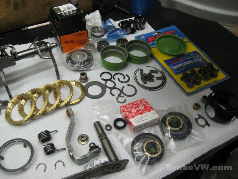
The taper bearings, shaft roller bearings, and the input shaft ball bearing have all been cryo treated after I get them, for additional wear resistance. The factory oil on them gets cooked in the cryo process, and gets thick and needs cleaned out. I use 3M brake cleaner to rinse them off, soaking them in a bag filled with the brake cleaner....
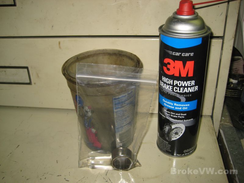
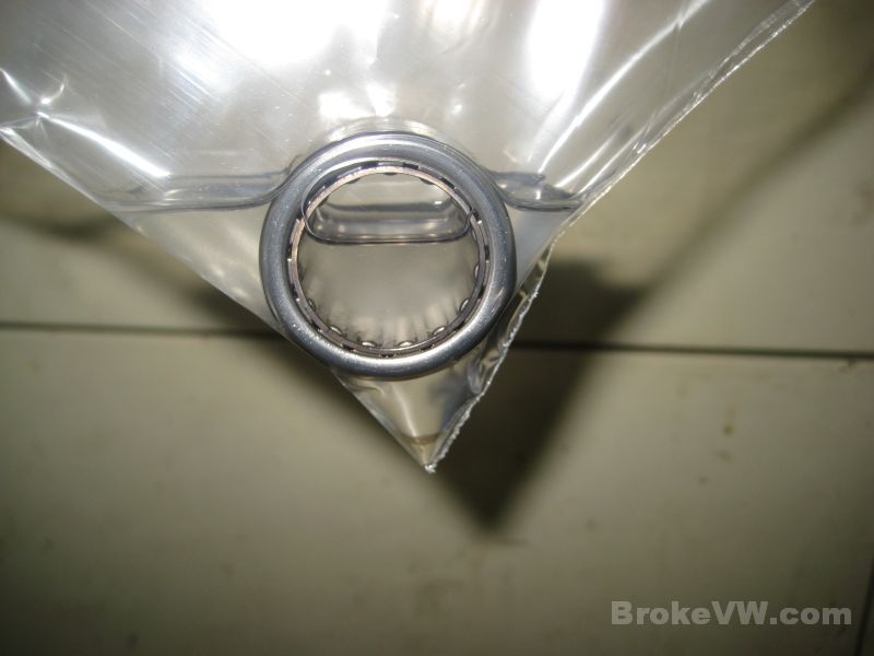
When they are good and clean, the clear brake cleaner will remain clear like water. When I first soak them, oily bearings instantly turn the clear cleaner into a murky soup. They are removed from the brake cleaner, dried with compressed air, then oiled. This is an example of a very clean roller bearing....
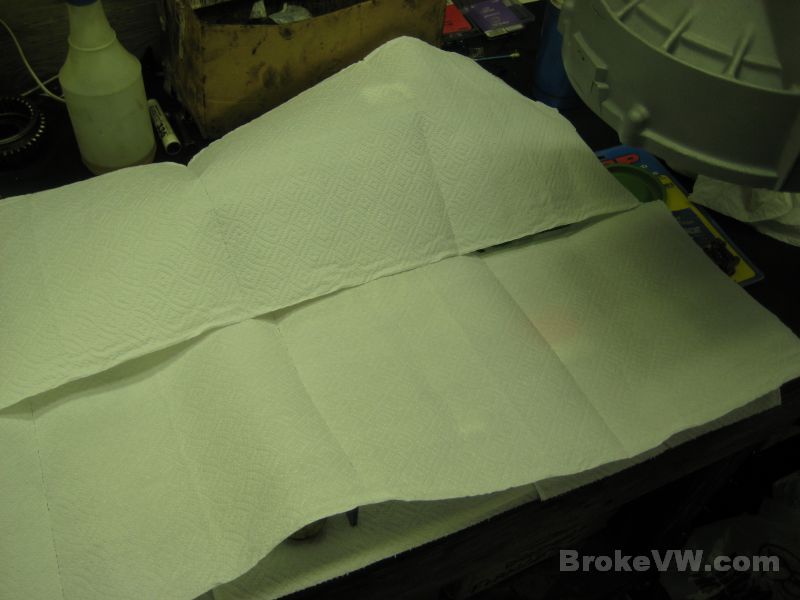
When I'm not working on it, the parts remain covered...
Next will be building the sub-assemblies... the shift forks, 5th gear, input shaft, and diff. After that the case will have the bearing races pressed in and the preload procedure can start.
The shift forks are assembled...
The ARP bolt kit is installed into the diff carrier...
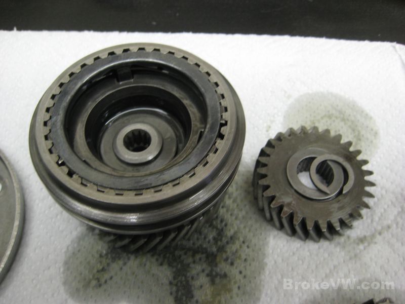
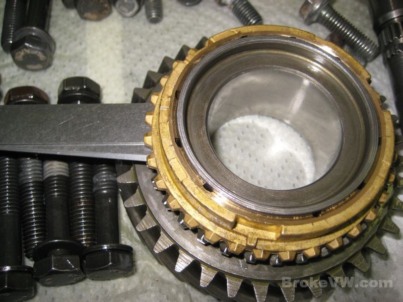
The 5th gear assembly is built with new keys, springs, bearing, and sync ring...
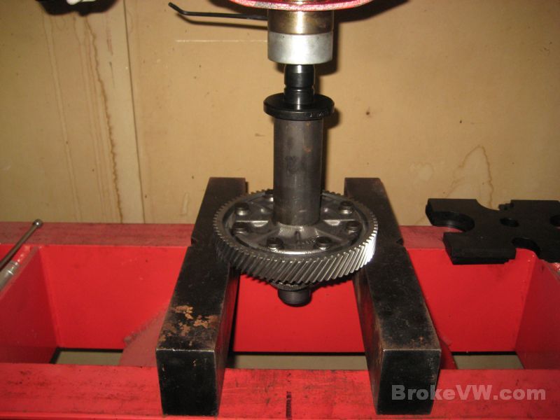
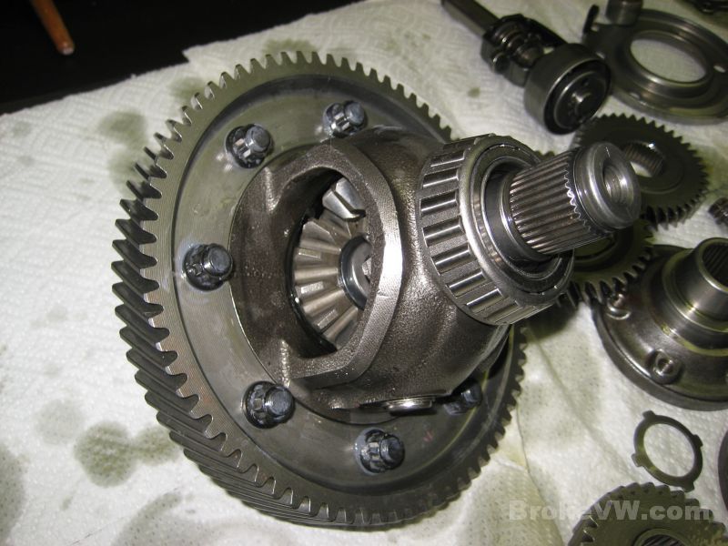
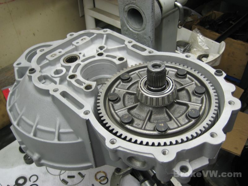
Installing the heated ring gear to the diff carrier...
With the ring gear in place, the diff assembly can begin with new 2.3mm snaprings, and a new plastic thrust washer...
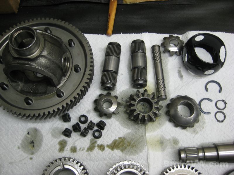
The cross shaft and small spider gears are installed after the new plastic thrust piece is in place...
The cross shaft is secured now with snap rings since the rivets are gone...
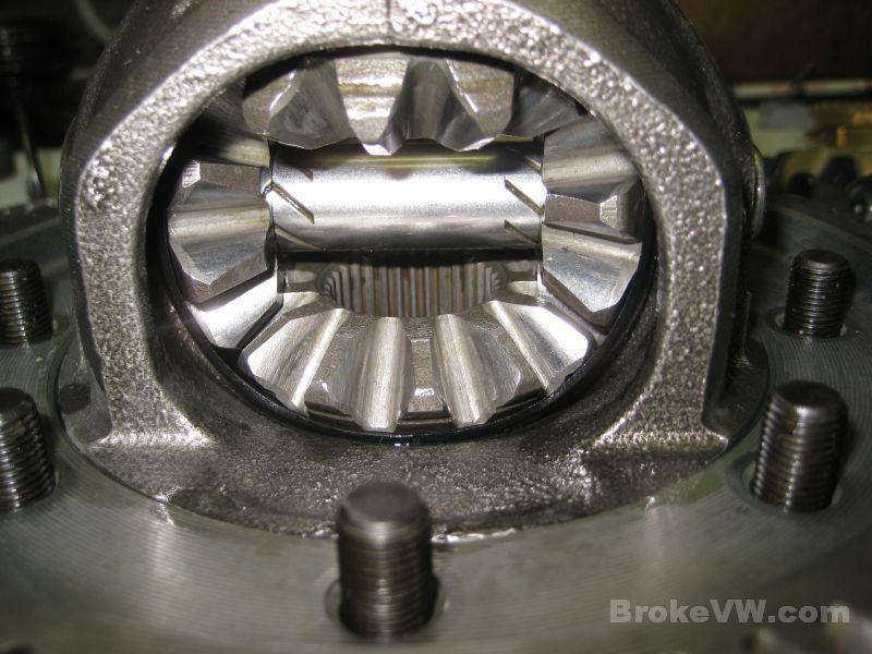
With the 2 small spider gears in place, the larger spider gears are inserted together into the carrier, then turned so they are on the top and bottom and lined up with the holes for the stub axles...
Prior to installing the stub axles, the heated bearings are pressed into place...
With the bearings on, the stub axles can be inserted into the large spider gears, and secured with 2.3mm snap rings. The diff comes with 2.0mm rings from VW, and 2.3mm rings are sold to take up any wear in the parts over time, so the diff is nice and tight like new. This pic shows the top shaft secured, the bottom shaft has not been...
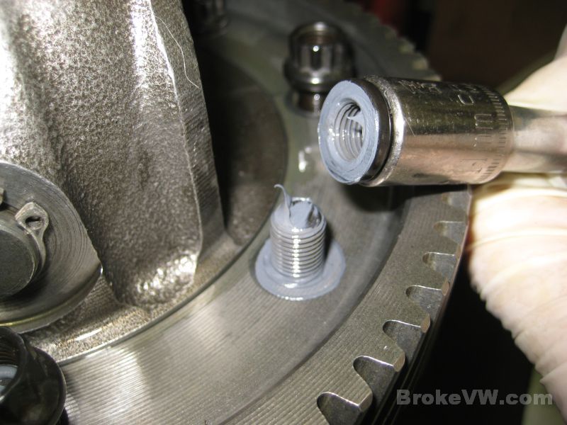
Now that the ring gear has cooled fully, the nuts can be installed. ARP doesn't use the same torque install figure VW calls for, due to the thread lubricant supplied by ARP that reduces friction. Much of the install torque of a fastener is needed to overcome the friction under the head of the bolt or nut, as well as the friction on the threads so if they are well lubricated, less ft-lbs will be needed to get the same clamping force. I run a little blob of grease along the threads, wrapping it over the top of the bolt to ensure it gets all the threads coated when you run the nut on...
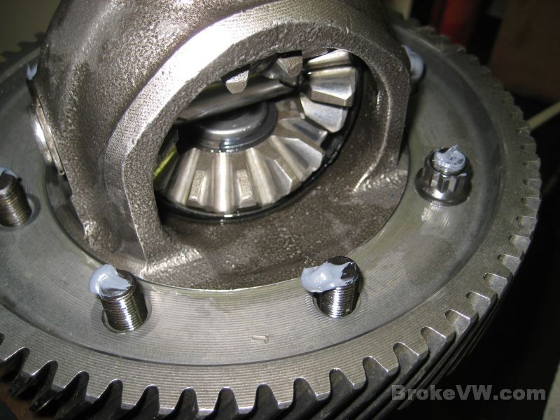
I sometimes like to test that things are going as planned, so I backed a nut off after installing it to check the dispersion of lubricant on the threads and under the nut, and this is exactly what you want to see...
The diff built and done for now, it will be bagged up until needed later...
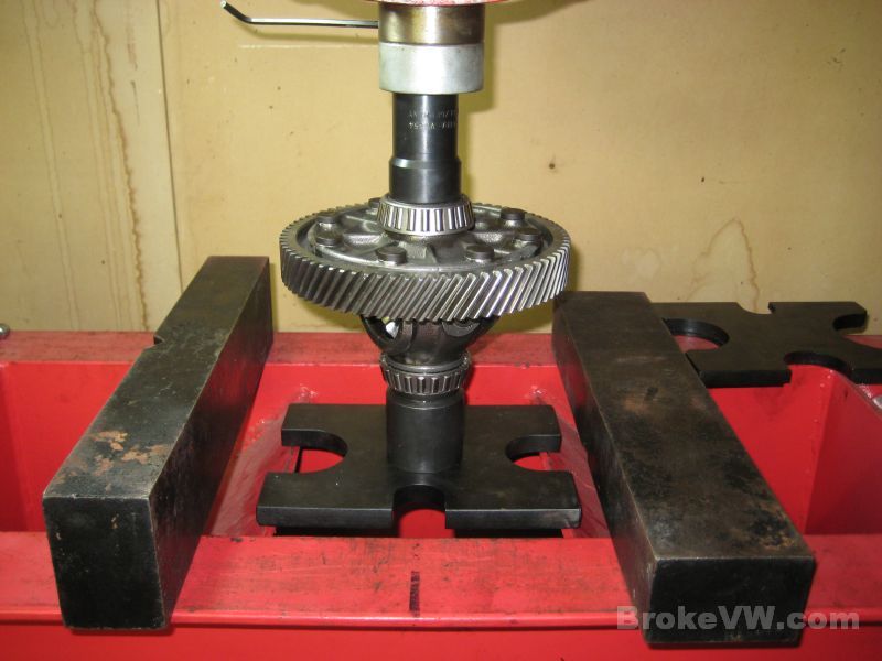
Heated along with the ring gear and carrier bearings were the output shaft taper bearings, so they are pressed on now...
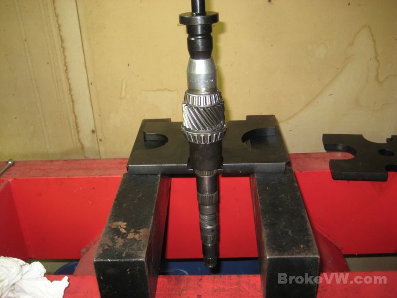
Time to build the input shaft, this is a tool I made from an old pushrod and a bolt welded together (it was for another job) and it works great to support the pushrod bushing and drive it in at the same time. Supporting the inside prevents the bushing from distorting as you press it in. The tool allows me to drive the bushing in flush with the end of the input shaft...
Once flush, the tool is removed, and inserted from below so it pokes up through the bushing, continuing to support the ID of the bushing as it is installed the rest of the way...
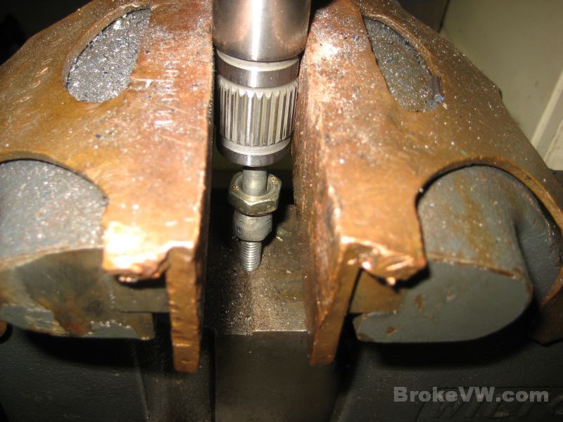
A deep 10mm 1/4" drive socket it used to fit over the pushrod and inside the input shaft, to allow the bushing to be driven in until it stops...
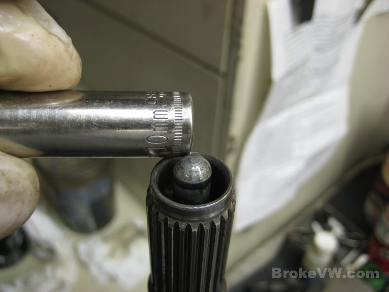
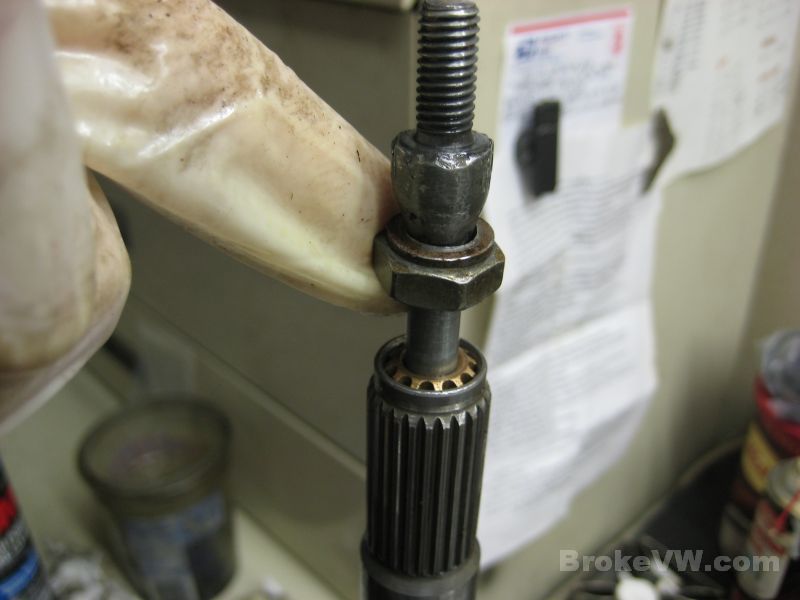
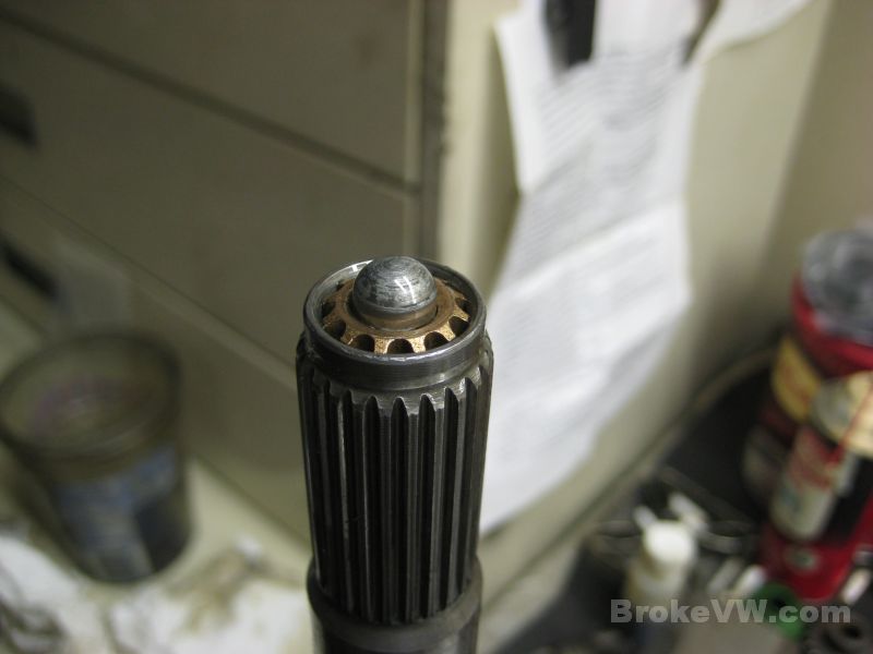
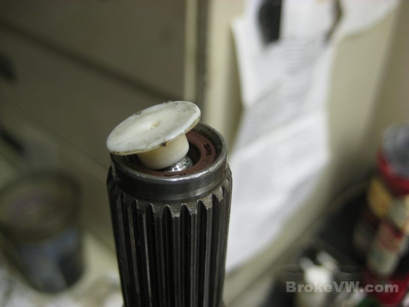
The pushrod seal is driven in until flush with the install cap/tool...

When the cap/tool is popped out of the seal by the pushrod, it leaves the seal properly installed 0.8-1.3mm below flush with the end of the input shaft...
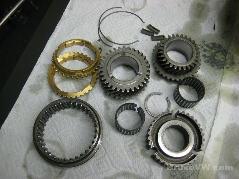
These are the parts that will be used to build the input shaft, a pair of new sync rings, a pair of new needle bearings, new springs and keys, and a new circlip...
Driving on the 3/4 sync hub once heated...
With the hub in place, the new circlip can be installed to secure the hub to the shaft, as well as the top sync spring...
Drop on the new sync ring for 4th gear after installing the 3 keys and the sleeve...
The completed input shaft, it is done for now and will also be bagged up until needed later...
The parts are starting to thin out now, with less needing assembled, and the new parts slowly being used up...
Update 02/29/12
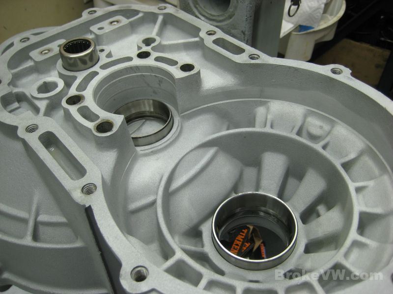
The bearings are pressed into the case pieces...
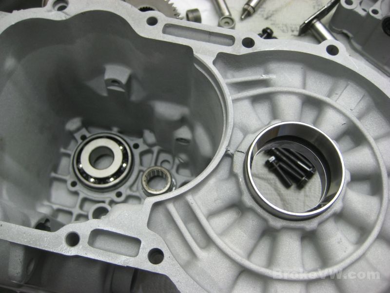

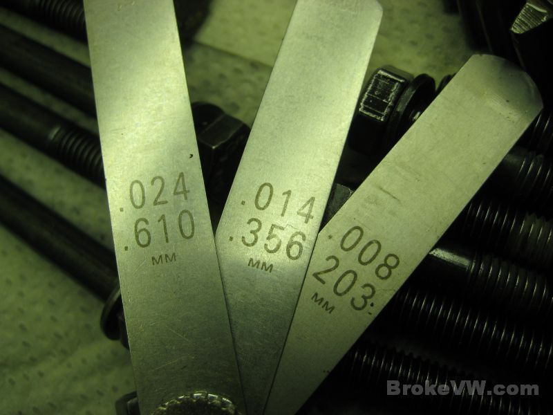
With the bearings in place, the preload procedure can begin. The original shim for the output shaft was too large, it was a 1.00mm and I used a 0.85mm shim to bring the output shaft into spec. VW wants it between 4.4 and 13.3 in-lbs and your bearings are at about 7.5 in-lbs, which I am happy with...
The output shaft is adjusted without anything else in the case to affect the turning torque reading...
With the output shaft adjusted, it is time to do the same for the diff bearings...
VW spec is 11-31 and I have yours set at just a little over 18 in-lbs so it is properly adjusted now...
The heated 1st/2nd sync hub is pressed into place, then the heated 2nd gear needle bearing race is pressed on...
I am checking the sync ring gap for the 2nd gear ring, as this is the one most often abused. VW wants at least 0.5mm gap, your gap is over 1.2mm so it is well within spec.
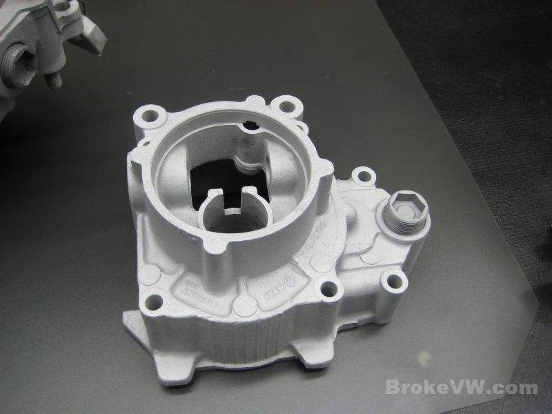
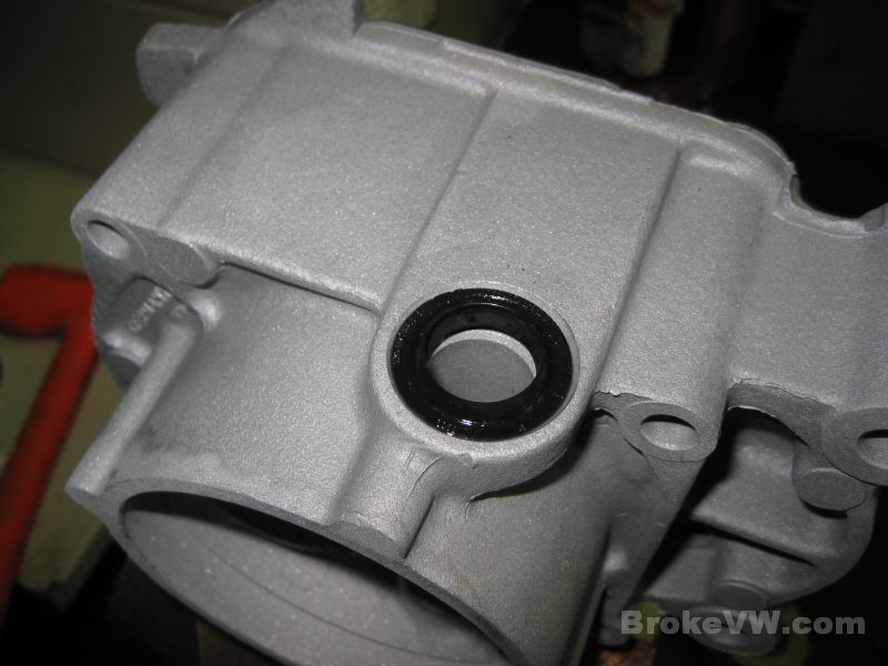
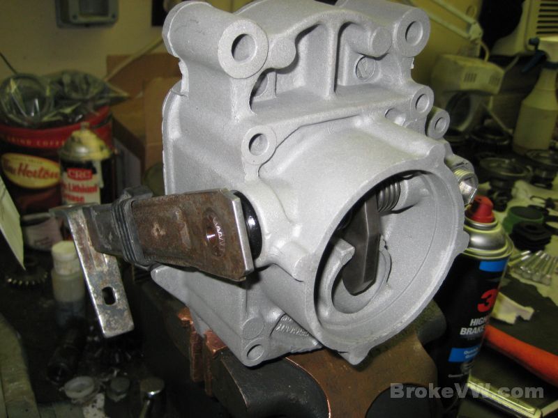
The 5th housing is partially assembled, but I had to stop due to a problem with one of the parts. The actuation fingers I received from a supplier were garbage instead of the usual OEM parts I would get there, so I sent them back and have some on the way from another source. Here is it mounted into the soft-jaw vise to allow me to drive the seal into place...
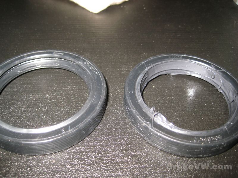
The seal above will be packed with grease between the sealing lips, as shown on the flange seal below on the right, the seal on the left has not been packed yet. All the radial shaft seals get this treatment, per VW procedure. It is to help trap any dust or debris that might get past the dust lip before it reaches the inner sealing lip...
Update 03/09/12
Continuing with the output shaft assembly with 3rd gear pressed in place and a 3.0mm circlip securing it...
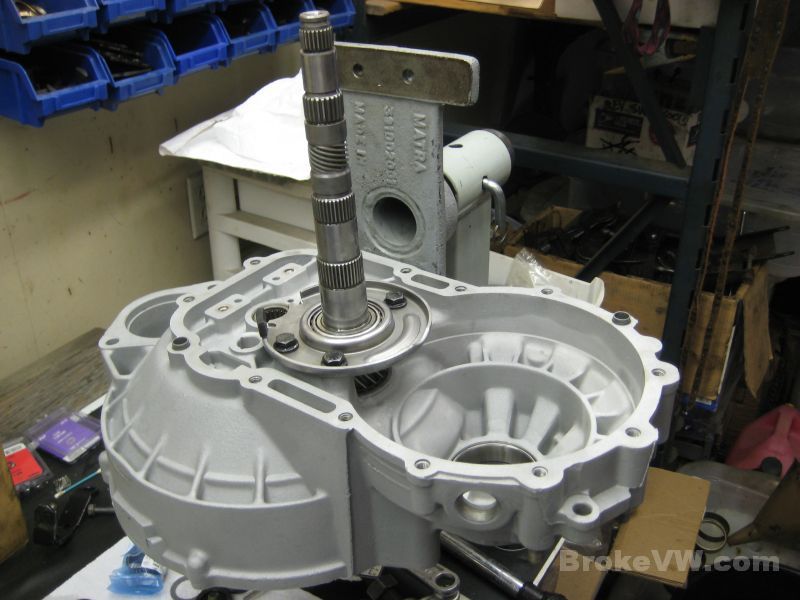
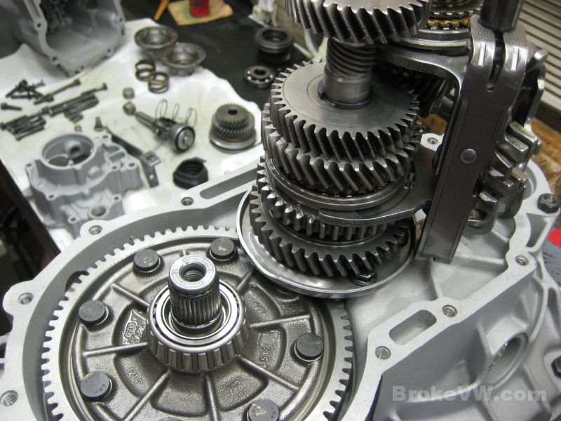
Next the input shaft is dropped in place, followed by the install of 4th gear on the output shaft...
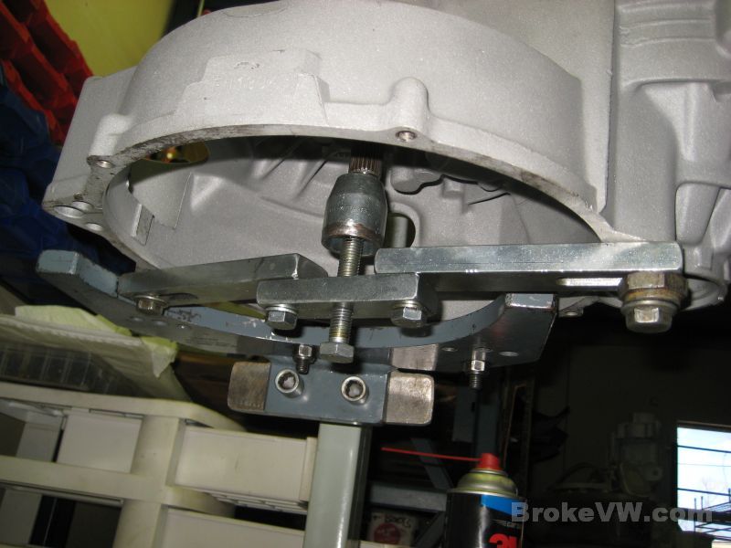
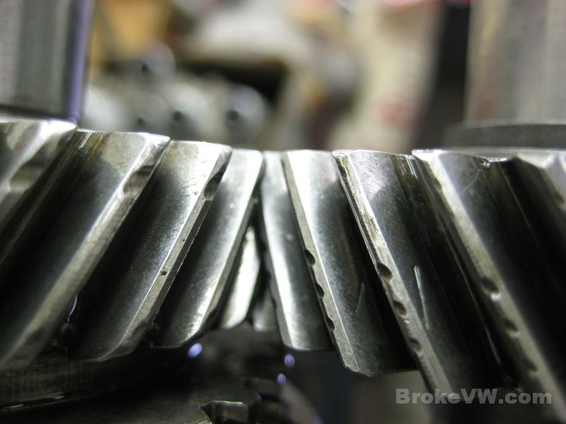
The gears don't align properly without adjustment, done via a heavy support bar bolted across the bellhousing. Once adjusted, the gear alignment is corrected and full tooth engagement is achieved....
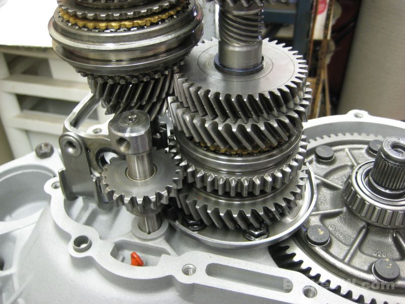
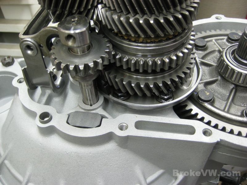
The reverse gear and replacement shaft are installed, along with a replacement relay lever. A spot of RTV silicone is used to hold the magnet in place...
The spring for the shift fork rod is dropped into the case bore...
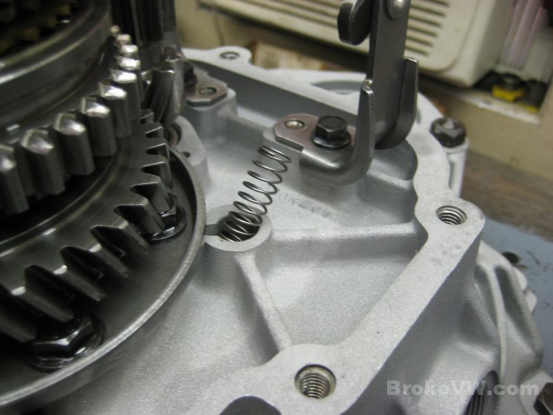
The shift forks are then installed...
What's left to install...
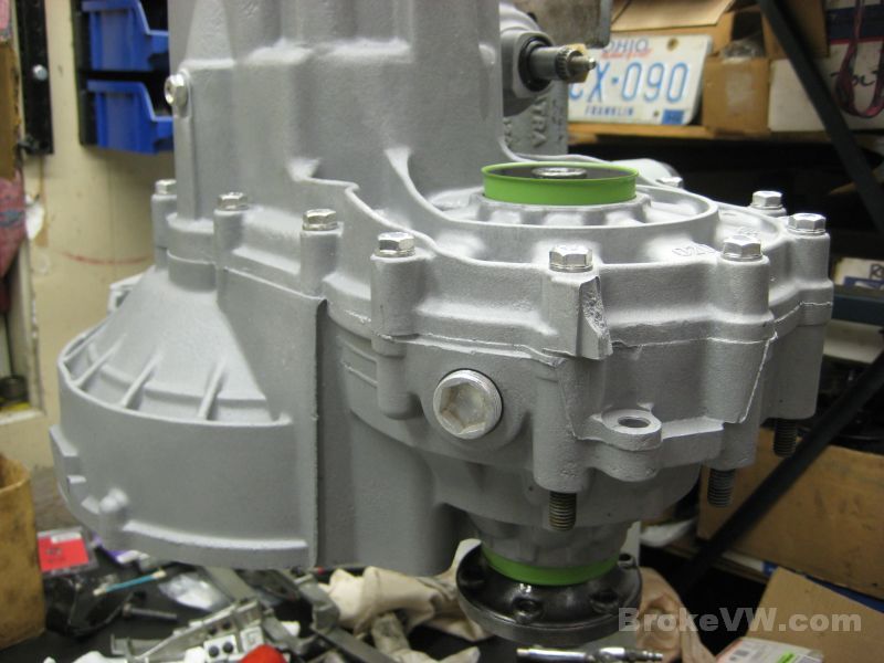
Let me know if you prefer not to have the silver drain plug shown in the 5th housing above, and the silver bolts shown below...
Next will be to clean the gasket surface and get the trans pressed together so the flanges and 5th gears can be installed. Once the selector is in place, I can install the reverse switch and test it with a multimeter.
Update 03/14/12
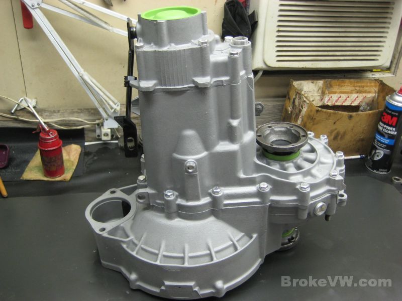
With the internal work done, the case is pressed in place and bolted, then the 5th gears are installed...
Adjusting the 5th gear shift fork...
Here is why I had to wait to build the 5th housing... can you guess which finger is OE VW, and which are crap Chinese copies?
The OE VW is on the left above, and the last finger in the pic below...
The new green end cap and plug along with the new actuation finger...
Locking the 5th fork after adjustment...
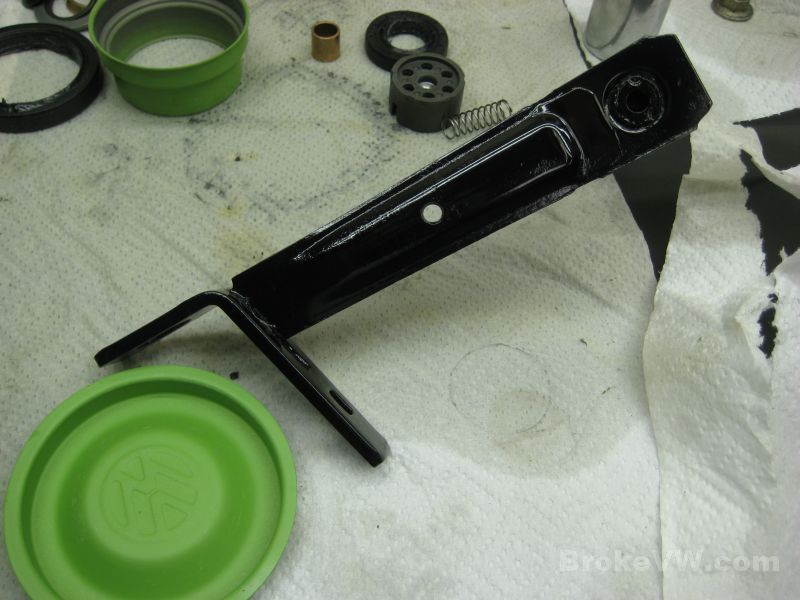
After putting the release arm into the housing, I didn't care for the look of it so I shot the arm with some black spray paint. It won't last but it looks nicer than the rusted arm...
The new selector seal installed...
5th gears installed with the TO bearing in place...
The 5th housing with the VW sealant paste applied...
The new input shaft seal installed... the pushrod wasn't replaced but it is showing signs of wear. I have new OE VW pushrods and can install one if you prefer...
The Peloquin shim kit shim being installed between the flange spring and spring cap...
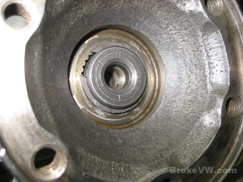
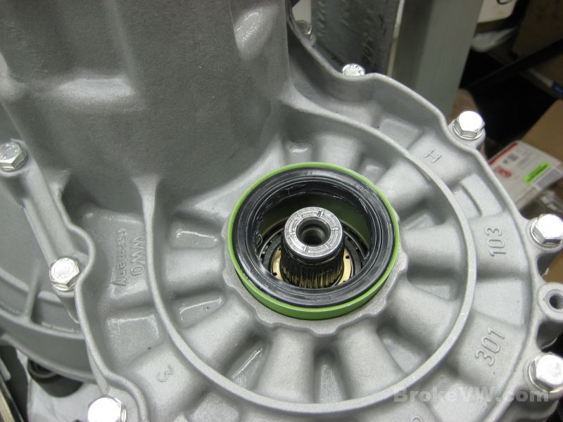
The passenger side green seal sleeve and seal installed with the Peloquin bronze thrust ring...
Compressing the spring to install the circlip...
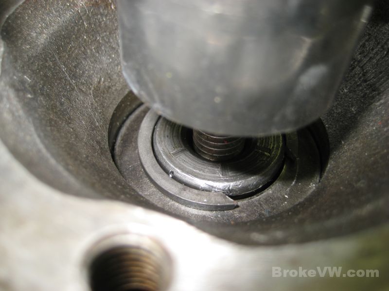
In the pic above, there is no concave washer under the circlip. Normally, with the 40% kit, the concave washer is used. I couldn't install the circlip with the washer in place, so it was left out. I'm not sure if there was a design change to the stub axles or the diff carrier or if it is just a product of the conversion from old style 90mm flanges to the new style, but the concave washers couldn't be installed.
In the pic below, you can see the circlip simply will not seat into the groove. I ruined a pair of circlips trying it, so I finally had to delete the concave washer to get the flanges installed. They are not used in the 80% kit, but normally can be used with a 40% kit...
The drivers side sleeve driven in...
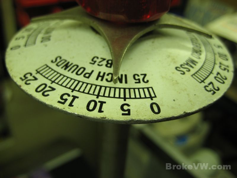
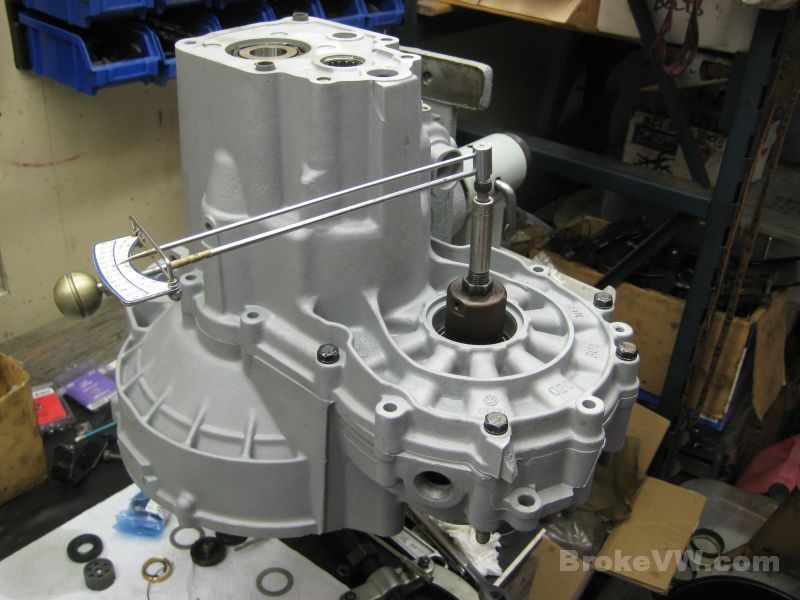
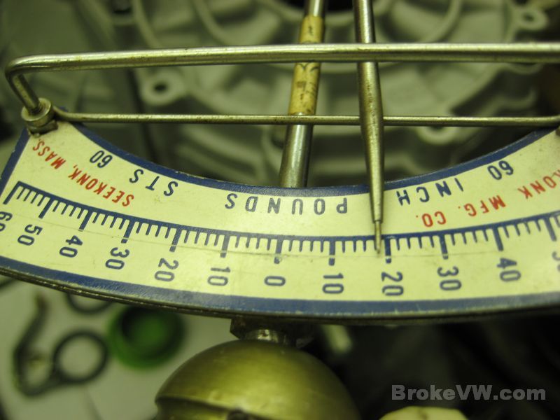
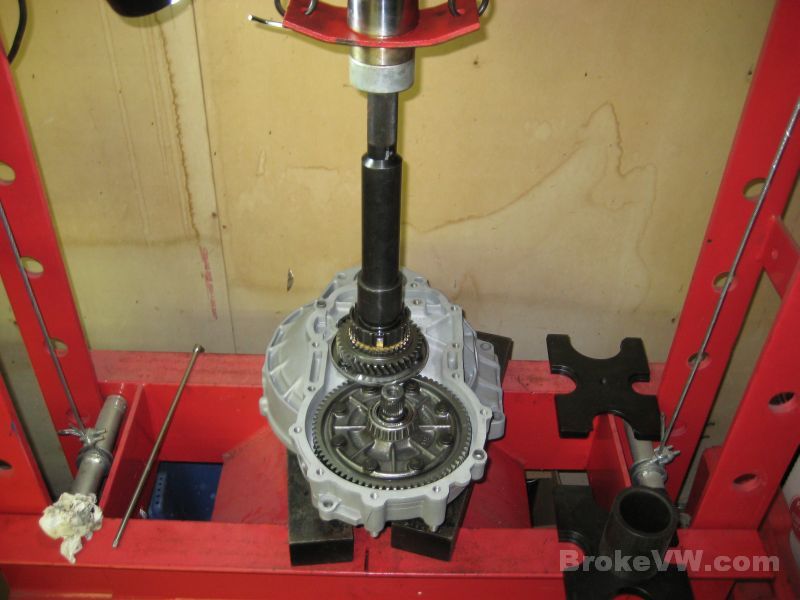
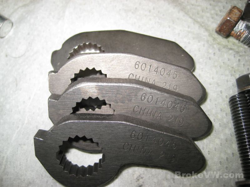
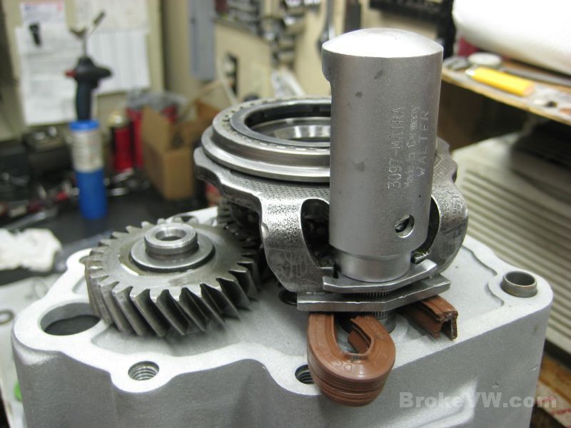
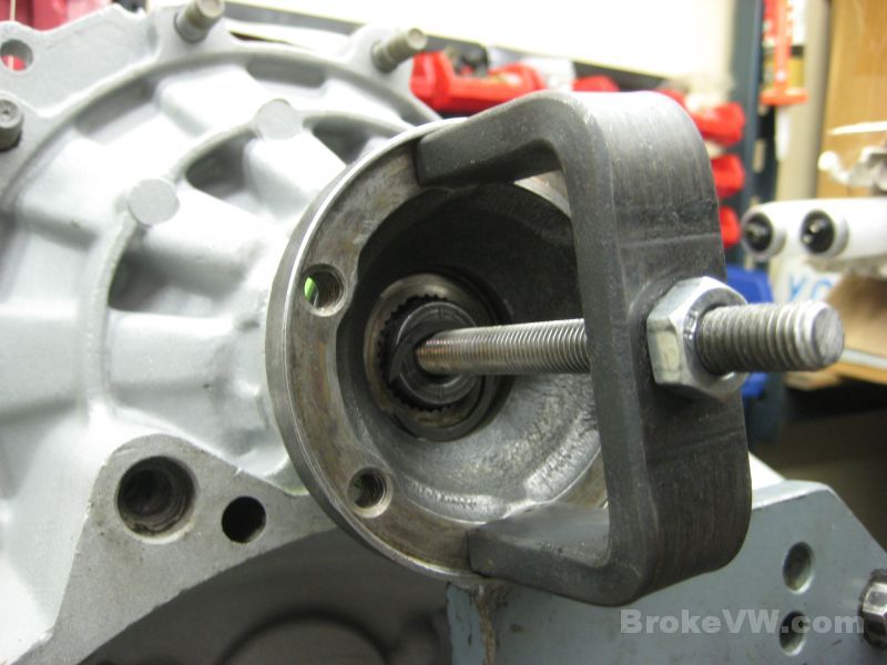
With the drivers flange installed the same way I then tested the break-away torque of the diff. One flange is held solid (the bottom one with the wrench preventing it from turning) then the other flange is spun and the torque measured that is required to spin the one flange.
Stock 1983+ torque is about 27 ft-lbs, your diff is at about 46 ft-lbs, which is an increase of about 70% over stock MK2 trans, and over a 1000% increase over the original FN break-away torque which was about 4 ft-lbs for the pre-1983 trans. It's basically 10x tighter than when it arrived here due to the parts change and Peloquin kit installation.
It isn't quite as tight as a 40% kit with the concave washers under the circlips, but the force needed to force the circlips into the grooves was too great so they were deleted rather than forcing something and causing a failure...
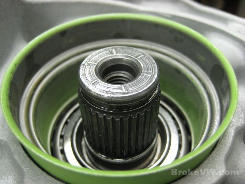
The center cap seals are installed...
The new starter bushing pressed into place. It has been lubricated by forcing oil through the porous walls of the bronze. You fill it with oil, then squeeze it between your thumb and finger and the hydraulic pressure inside will force the oil through the bushing walls where it sweats out tiny droplets of oil. The oil is dumped from inside and the metal is left impregnated with oil which will provide lubrication to the spinning starter motor shaft...
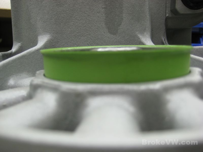
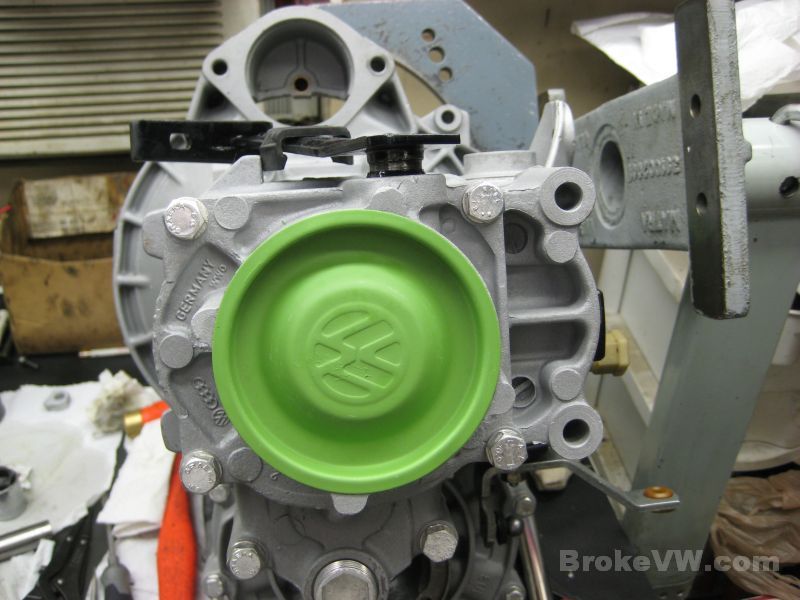
One of the last parts to be installed is the VW green end cap...
Here are the parts left over which is the shaft linkage piece that needs installed, then the 2 caps and bolts that constitute the 80% kit. Also shown is the broken piece of casing from the original shipping damage. Not shown is the chunk of speedo cable that was installed into the speedo hole...

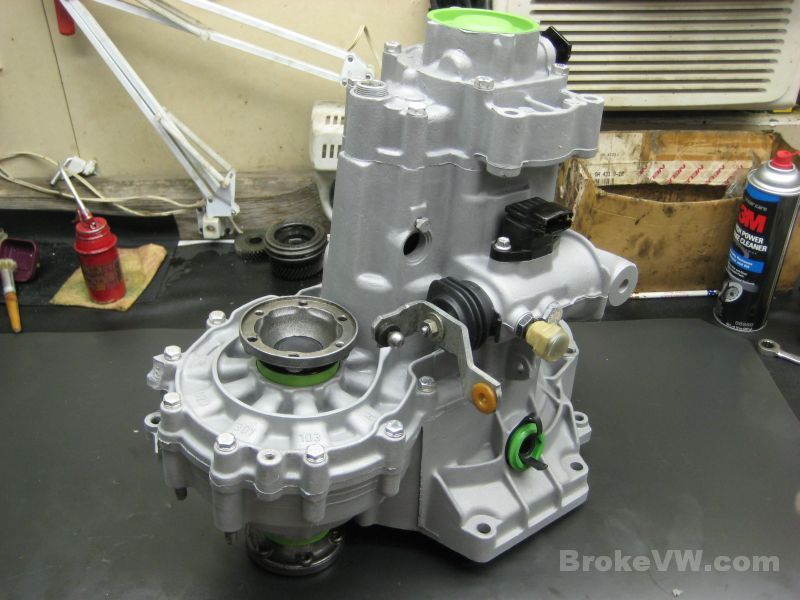
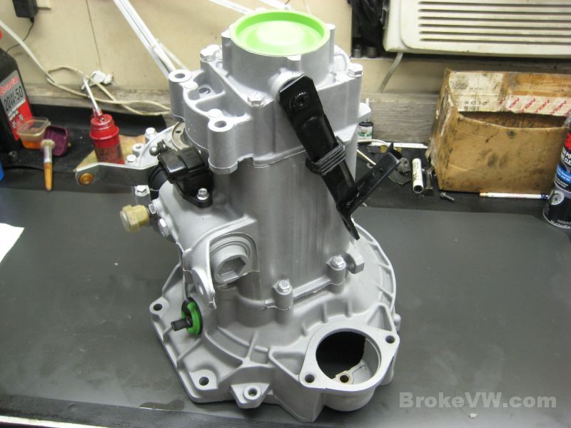
All done, I just need to install the shift linkage bracket and pack it up... the reverse switch was tested and it completes the circuit when in gear and breaks it when it isn't, so it is working like it should....
Update 03/14/12
I have it securely packaged, it should make the trip safely.
The new OE VW pushrod has been installed...
The linkage pieces are installed, but they could probably use new bushings... I hit the brackets with the same black rattle can paint, so don't expect them to stay black for long...
Bagged up and ready to box...
The box is made from 3 of the same-size boxes. I used 2 of them, doubled up inside each other, then a 3rd box is slid over that for the top. The padding is carpet padding. It can take a shock, won't crush, and is stiff enough to hold the weight. You can also cut and roll it to make any size you need. I used 4 layers on the bottom of the box, then put the trans in on it's side and packed it in tight....
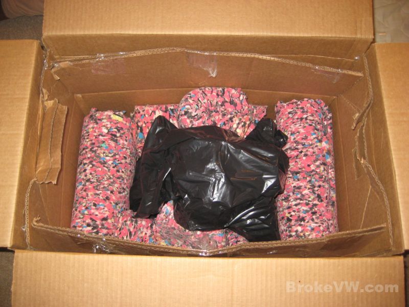
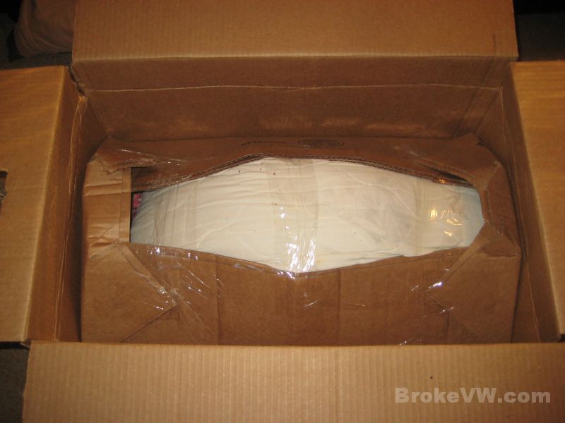
On top, I'm afraid to say you get the vanilla pillow. It is a pillow I received in a package that contained a 40 pound Sony stereo, so it is being recycled to you. I don't know who owned it last, but they REALLY liked vanilla perfume or air freshener or something. The double box is then folded up and taped to keep everything tight so it can't shift around...
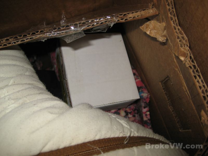
That is then cut open so I can put the box in I had forgot
originally :)
It has your 80% steel caps, a pair of stock concave washers in case you want to
try to install them later, and the flange install tool that comes with the
Peloquin shim kit. It will compress the flanges so the circlip can be
installed... I packed that into the original Peloquin box and tucked it
inside...
The top flaps of the outer 3rd box were cut to fit right on top of the inner double box and taped down, then I wanted to make a 2nd bottom for the original box, so I used 3 layers of carpet padding and made another box bottom, which is taped to the original box. There is about 2 inches of padding under the trans, then a doubled up box, then another 1.5 inches of padding, then another box bottom... so it should be able to take a decent hit and not poke through the bottom or sides....
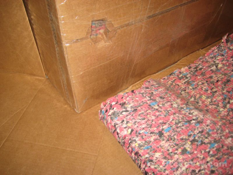
I cut handle holes into the sides so they can move it, and hopefully prevent it from being thrown and dropped...
It is heavier than the original package though, so UPS might want some money if someone catches the weight difference between the call tag weight and the actual weight.
The original package was no good, the trans had poked through it in several spots and the peanuts had crushed...
All ready and waiting to ship out...