Yamaha 350 Warrior Switch Assembly
The switches on the clutch lever of the ATV are for both the parking brake and the clutch lever, to tell the system when the clutch lever is pulled or when the parking brake is applied.
The switch is just a pin that is depressed when the lever is not pulled. Pulling the lever allows the pin of the switch to pop out which will connect the 2 wires inside and close the circuit.
The parking brake switch, when the circuit is closed, will cause the bike to start and idle, but rev poorly and backfire to prevent you from trying to ride with the parking brake on.
The clutch lever switch, when open, will stall the bike out if you are trying to select reverse gear, and it won't allow it to start again until the circuit is closed by the pin popping out as it should, or if it is out of gear.
My 2003 Warrior started to stall on me when reverse was selected, even with the clutch lever pulled. I found the problem to be with the switch.
The wires had been damaged, allowing the elements to get inside the switch and make the contacts dirty. I didn't get any pics of cleaning the bad switch up, but I decided to check the other switch for the parking brake to make sure it was in good shape.
Yamaha did a good job on the switch it would seem, my parking brake terminals were very clean and in great shape, so the factory managed to seal them up well.
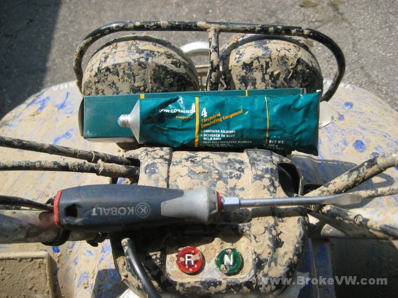
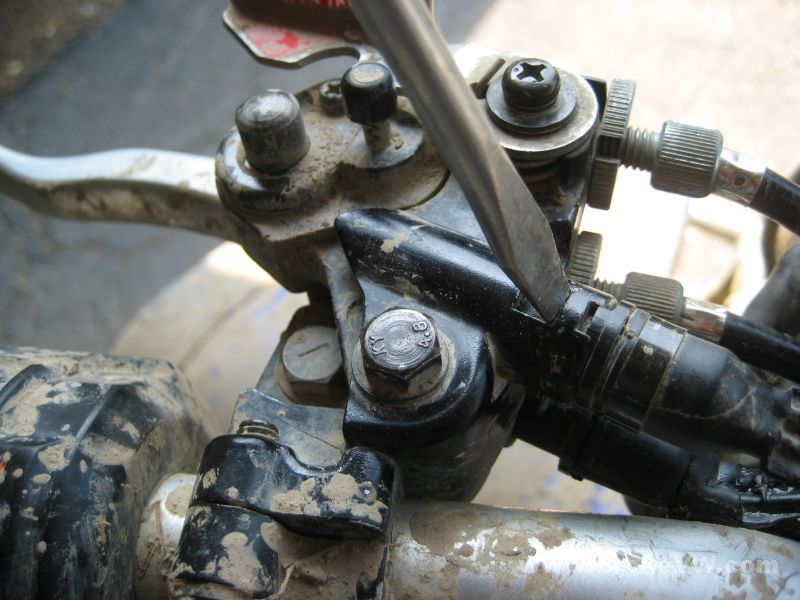
This is what I used to take them apart and clean them, along with a few paper towels. It is a medium flat blade screwdriver and a tube of electrical grease...
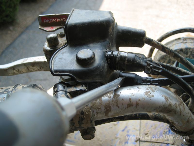
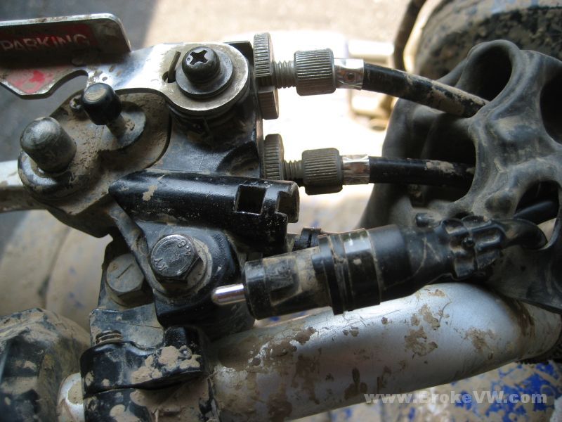
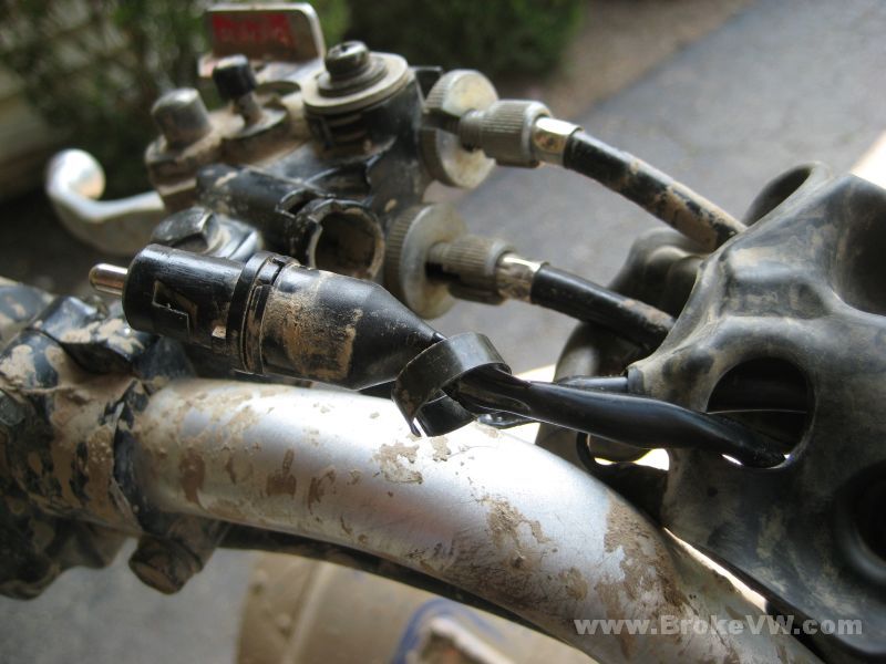
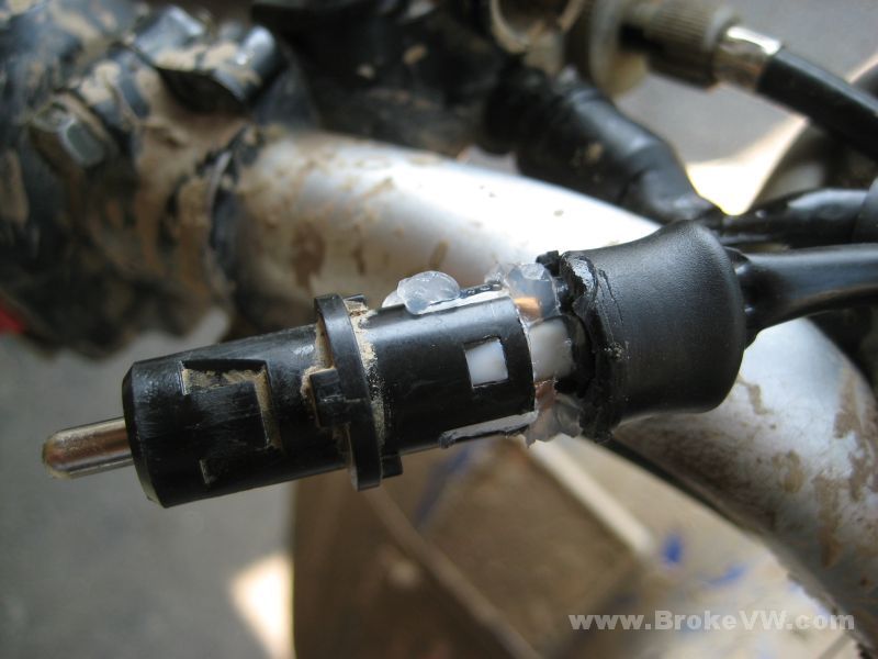
Here are the switches, the clutch switch is being pointed to, the parking brake switch is above it...
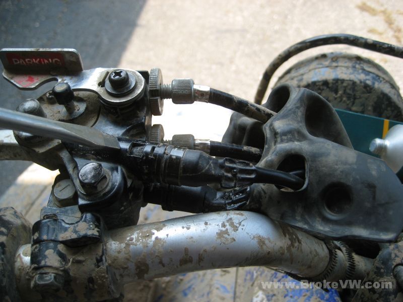
Peel the rubber boot back and find the locking tab for the switch....
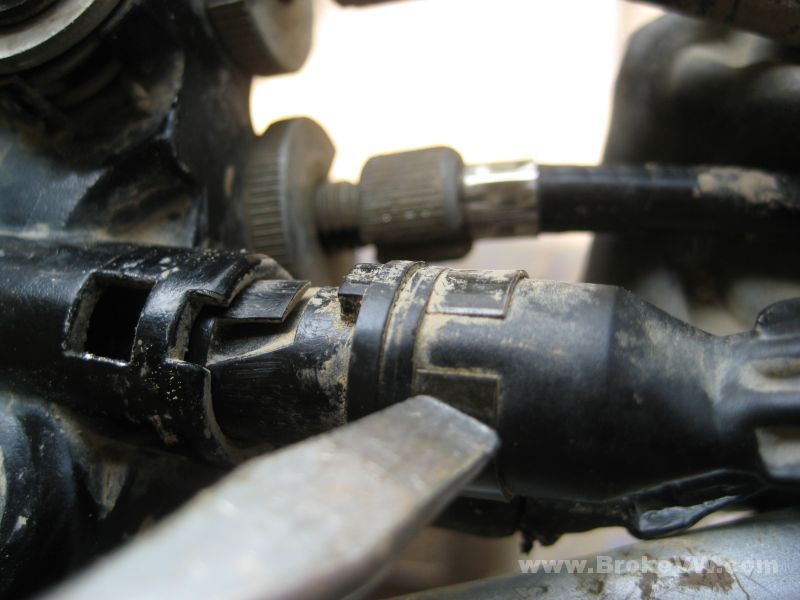
A close-up of the locking tab to release the switch....
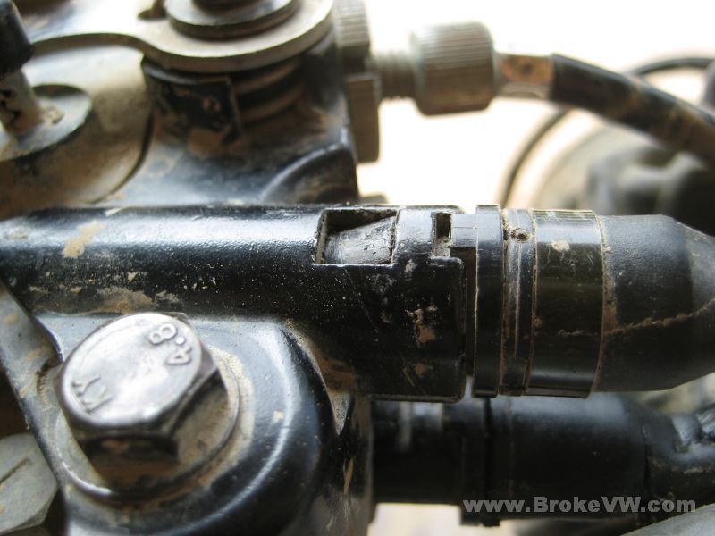
Depress the tab as shown here with the screwdriver...
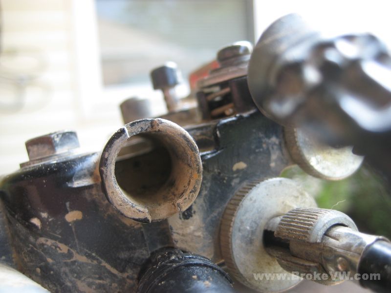
Slide the switch out...
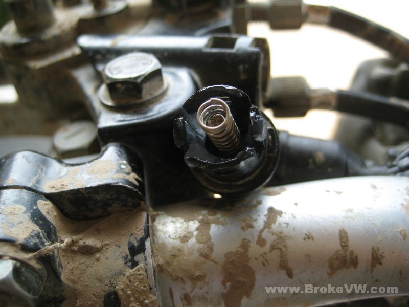
Inside the holder for my switch it was very dirty, so the elements have been making it to the switch all these years, but it has stayed sealed up well....
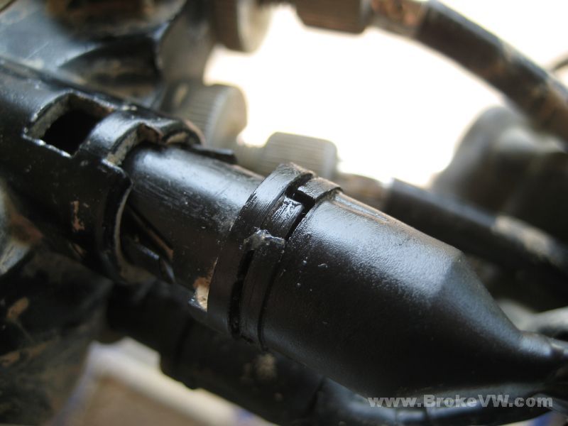
Locate the small spring-steel band around the boot on the switch wiring...
Slide it off and out of the way...
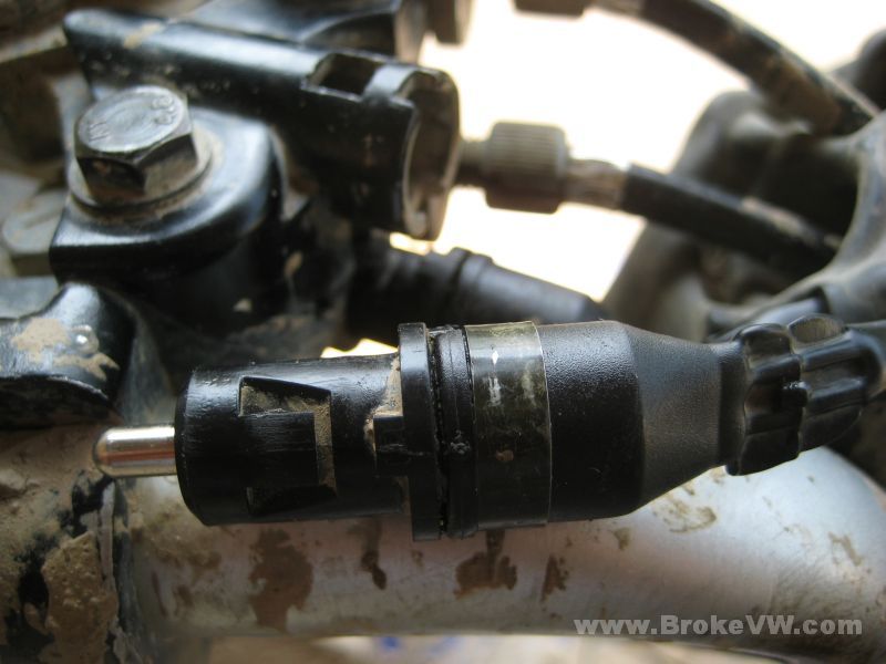
With the band removed, start working the rubber boot back and down. This can be tricky because the boot is small. Once the boot is out of the way, you'll see the switch assembly...
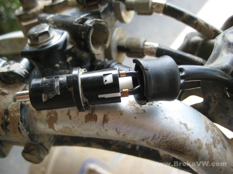
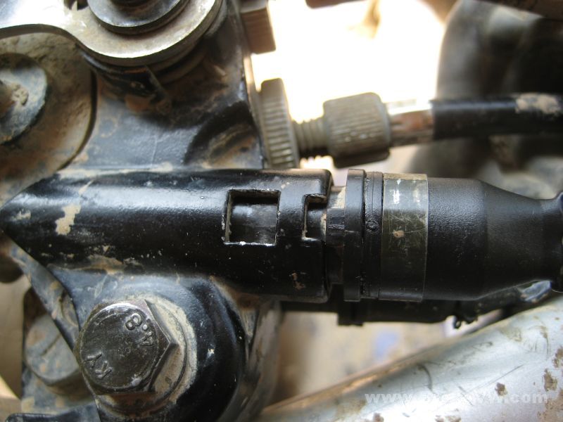
Locate the 2 white locking tabs that hold the switch together. This time, instead of depressing the tabs, you'll gently lift the black plastic portion so the tab can be unlocked...
You have to lift both sides at the same time, and the switch will slide apart....

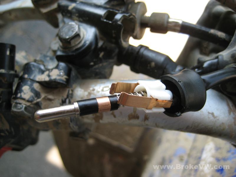
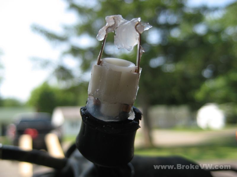
I've assembled the parts of the switch back onto the wiring so you can see how it is assembled. The pushpin has a thick black insulator, then the copper conductor, then a thin insulator, and finally the spring. The white plastic holder secure the 2 wires and those spring-bar contacts. When the spring bars contact the copper conductor, the circuit is closed and the wires are connected.
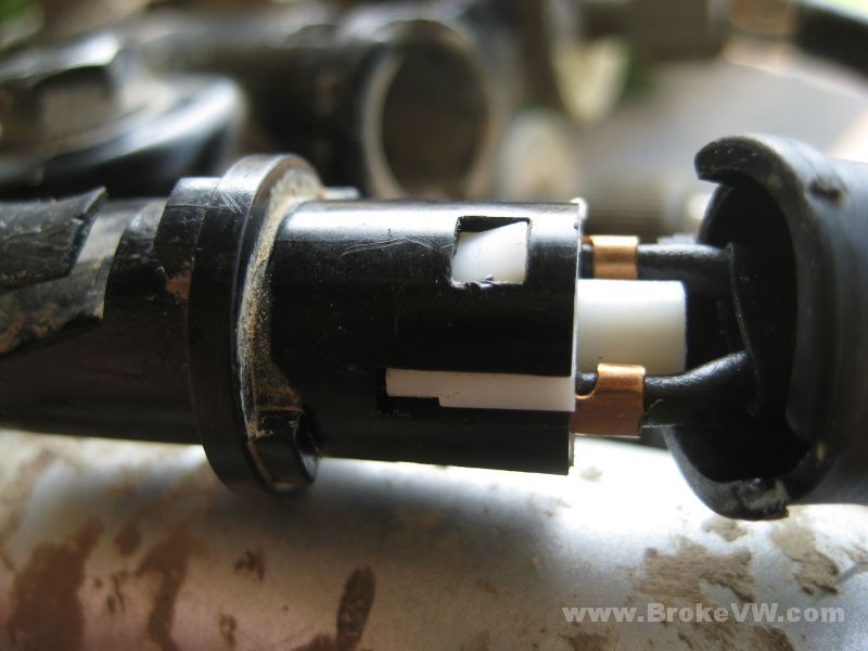
Clean the conductor and spring-bars if dirty so they are fresh and shiny again. These are how they looked on mine, on the good switch. The bad switch had gunk inside and the inside of the spring bars as well as the copper conductor were black with dirt and contamination...
For the assembly, put the pushpin and parts back into the black half of the switch assembly. Prior to installing the pin, I filled the holder with the electrical insulating grease...
On the white half of the switch, I covered the spring-bars, and also the crimps where the spring bars attach to the wires. The spring-bars simply snap into the side of the white holder and are easily removed if needed....
Mash everything back together, ensuring both white locking tabs engage and lock, then slide the boot back over the switch assembly...
Wipe away any excess grease...
Make note of the index notch on the boot for the tab on the switch when putting it back together...
Slide the metal band back in place over the boot...
Align the index notch and tab when installing the switch into the clutch lever housing...
Pull the big rubber boot back over everything, and you're done. The switch should now operate properly and be protected for years to come. Be sure to check the ground location as well and ensure that connection is clean, or the switch can still act-up and cause problems.
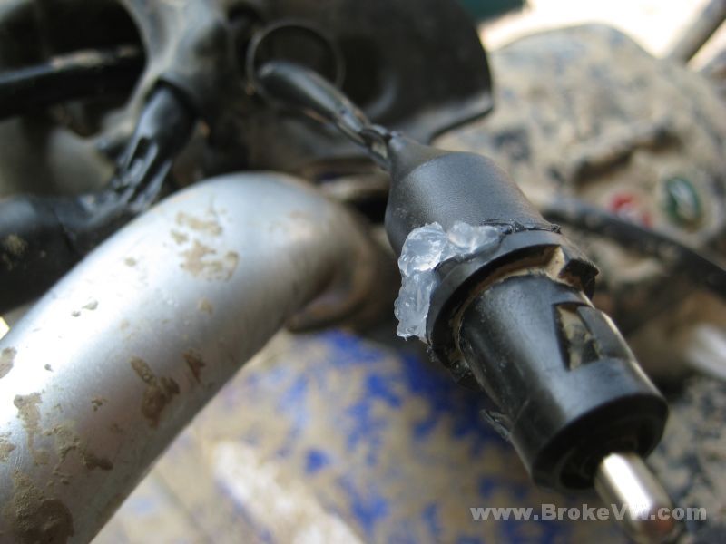
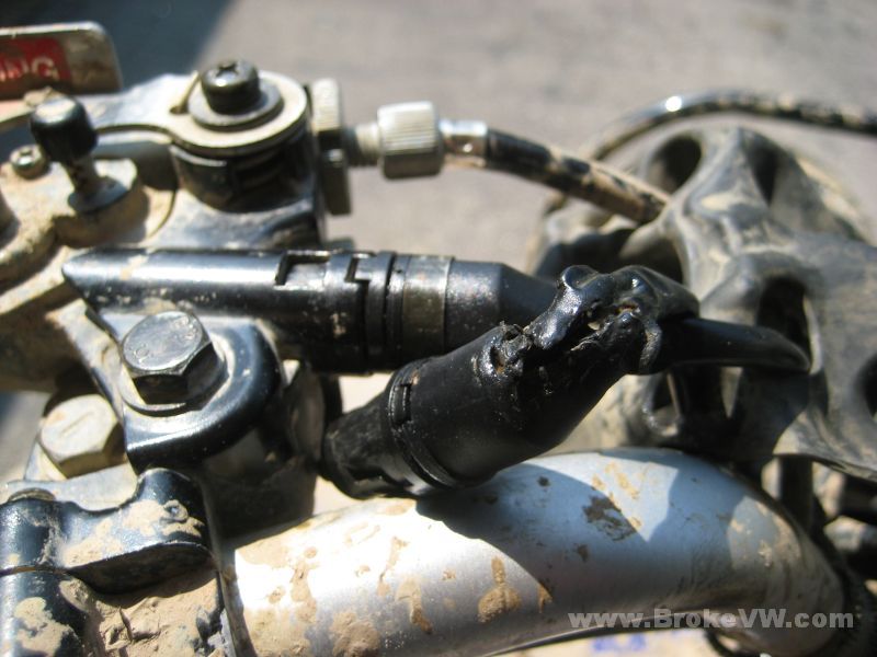
This is my clutch switch, you can see the previous owner has damaged it, and the elements have gotten in. I covered it in the insulating grease and wiped it down, then ran a film of red RTV silicone over the boot and damaged wire insulation to try to re-seal that section of the wire.
The cost of a new switch and wiring harness is about $30 as of 07/2011...
Oh... Disclaimer :)
I've owned this ATV for only 3 weeks now, and haven't owned or worked on one
since I was a kid with a brand new 1985 Suzuki LT125 Quad Runner. A good 20
years between owning one... so I'm not an expert by any means on the Warrior
or any ATV, but maybe the pics will help out!