Stripping the 020
This page will show the basic steps of opening the 020. The page is mostly for reference to be used in addition to the Bentley manual or another suitable copy of rebuild procedure for the 020.
Because of the variations between the various codes used for the 020, not all of the pictures will match what you might find inside your trans.
This page will cover opening the trans after the flanges and 5th gears are removed. To get those parts off, follow these links to the pages showing that procedure.
Here are a couple home built trans tools that someone built and sent me pictures of... these are available for rental, you can email me at brokegti@sbcglobal.net for more info. See them HERE
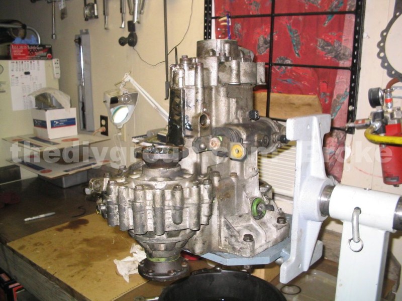
OK, start by draining the trans of any and as much oil as you can. You won't get it all out, but get what you can removed. Once it is drained, the trans can be mounted to a stand to begin work.
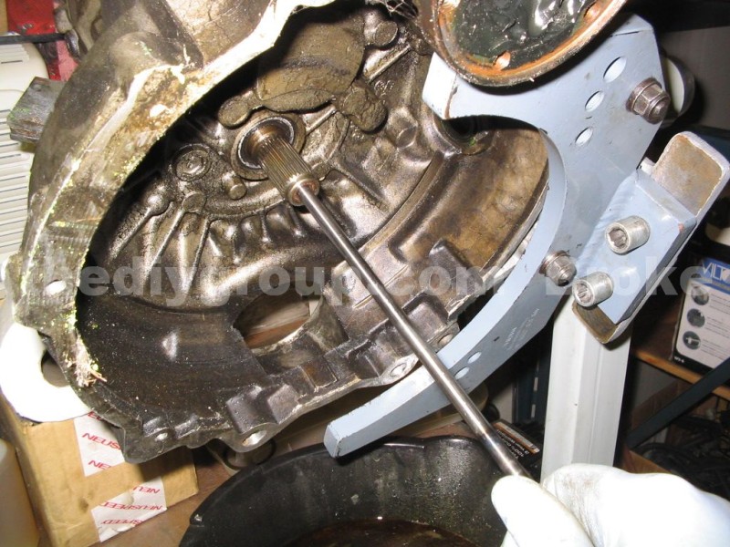
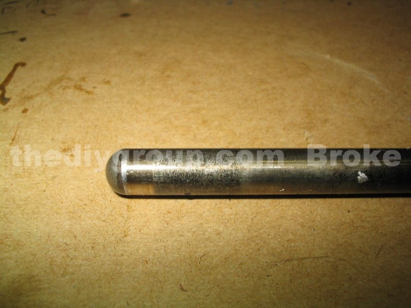
Remove the pushrod by pulling it out and notice that one end of the pushrod is perfectly rounded, while the other end is slightly tapered before being rounded. This smaller tapered end should contact the thrust release plate, and the perfectly round end should fit the TO bearing.
If you flip the rod, the smaller end won't fit properly into the TO bearing, and won't distribute the load across the entire bearing cup, and the TO bearing can fail. Aftermarket pushrods generally do not have a tapered end as the factory rods do (recently I have ordered aftermarket rods, and one end was tapered like OEM, so that statement doesn't ring as true as it once did). Both styles will have blued ends, and this is not a fault, this is just the result of the factory heat treatment to harden the end of the rods.
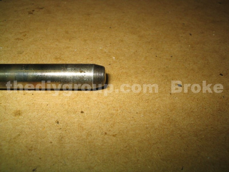
The tapered end to the thrust plate (this rod is worn, and flat on the end, instead of rounded)....
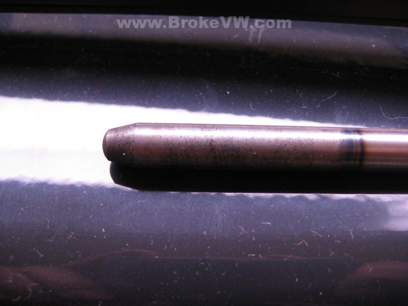
This is what a new pushrod should look like on the tapered end...
The rounded end to the TO bearing...
OK, dig all of the grease out of the flange, and follow this link to remove the flanges...
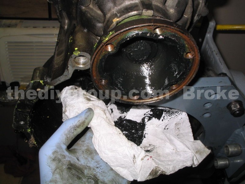
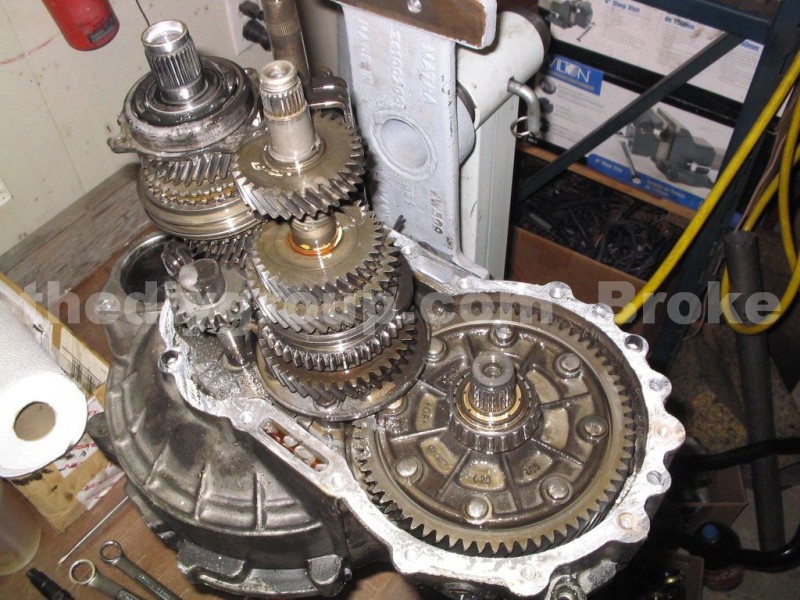
After you remove the 5th gears and end case as shown on this page you should be looking at the trans as shown....
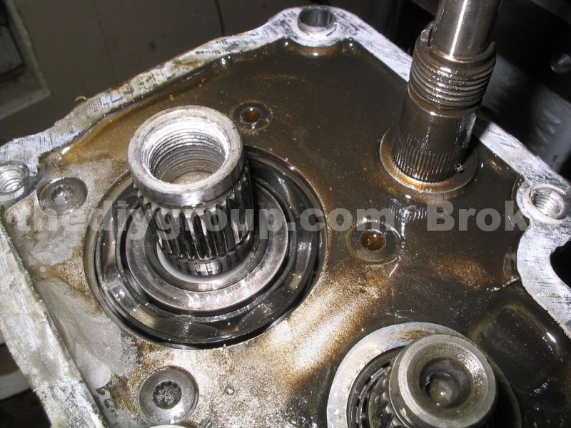
Use a GOOD quality driver to remove the 4 bolts that secure the large bearing clamping plate inside. These bolts are easily stripped, and usually in there VERY tight. If you notice in the pic above, the 2 bolts to the left have been cleaned of any fluid in the head, and the 2 on the right are still full of fluid.
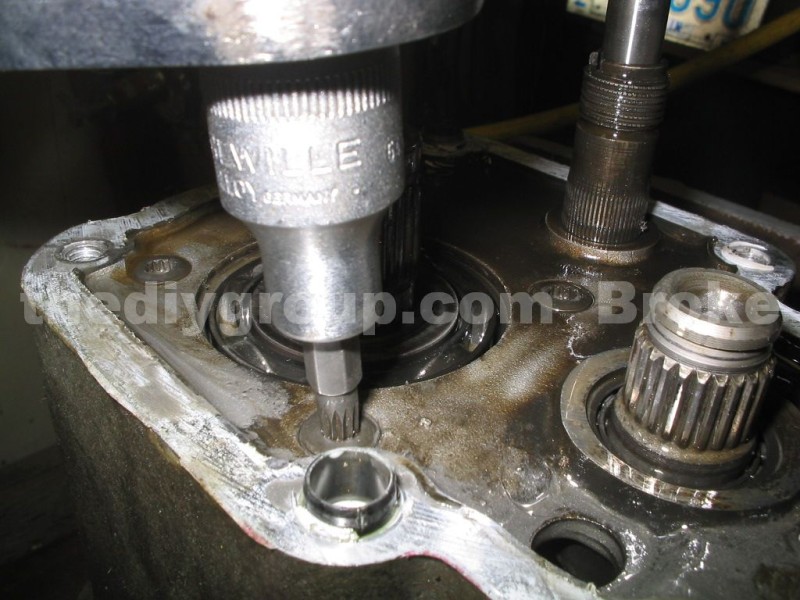
If you do not remove the fluid, the bit will try to compress the fluid in the bolt as it is inserted, and as proven with the hydraulic braking system, fluids do not like to compress. The result is the driver won't fit fully into the bolt, and it'll round the bolt out.
The bolts are XZN bolts (also called triple-sqaure or 12-point) in 6mm size.
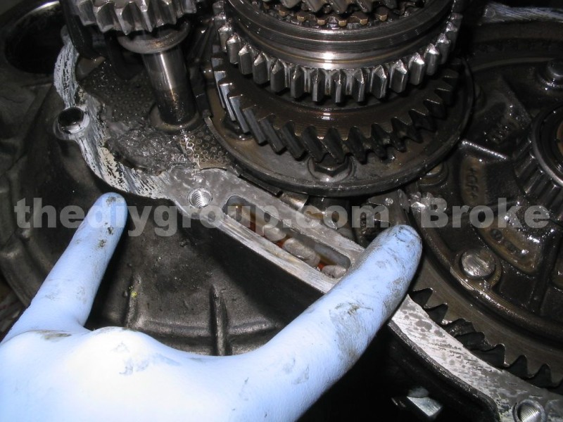
Remove the reverse bolt that secures the reverse idler shaft inside the trans (the shiny round hole in the middle of the case in the pic below), and remove the case bolts around the case edge.
The case bolts are all 13mm, and the reverse bolt could be a 13mm or a T-47 Torx bolt.

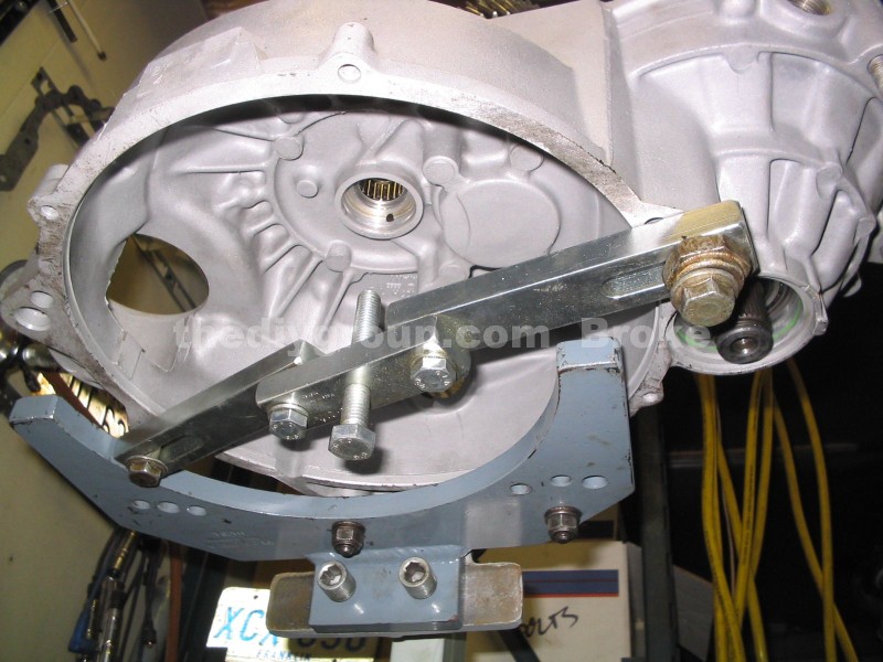
Now is the time to install the input shaft support bar. This allows the force of the pressing operation to follow to not be transmitted to anywhere but through the shaft and into the support arm.
This pic was stolen from the rebuild portion, because for some reason I managed to lose the pic showing the support being used on the dirty trans. Install it as shown, then tighten the center bolt up until it just supports the weight of the input shaft. VW calls for the VW295A adapter to be used between the bolt head and the input shaft end, but as long as it is a good solid support and not damaging the shaft, it'll work fine.
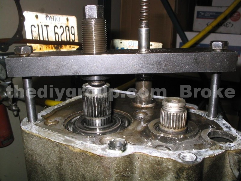
Install a case splitter tool as shown, threading the 13mm bolts into the holes for the end cover, and aligning the screw over the input shaft. Tighten the case splitter until the case splits and the main ball bearing will stay on the shaft.
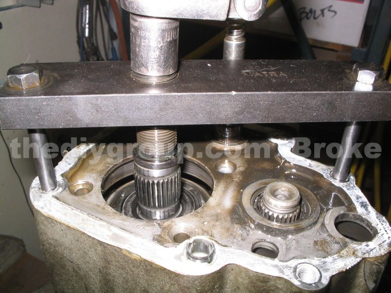
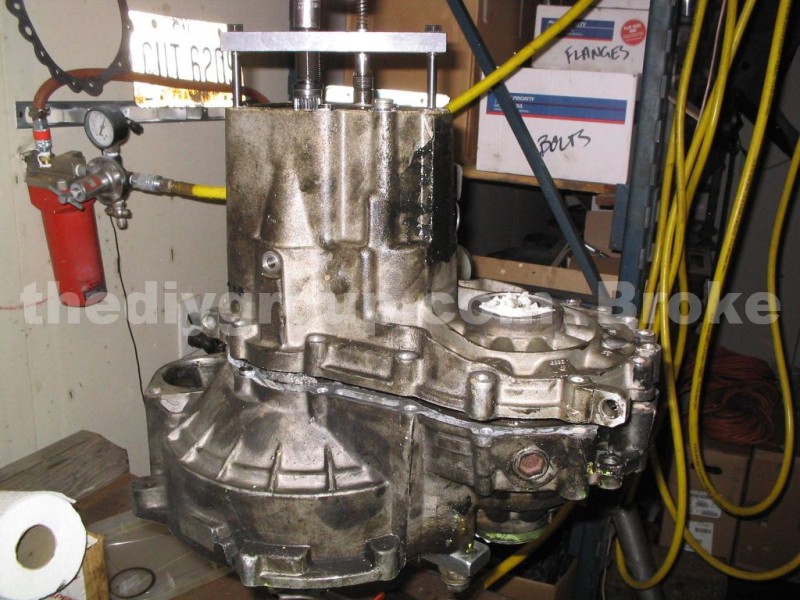
Now you can lift the gearbox off of the bellhousing, exposing the input and output shafts....
Here you can see the magnet covered in metal, and chunks of teeth, and a couple missing teeth from the ring gear.
OK, the case has been opened and the shafts exposed, next is to remove the shafts from the case.... click here to go to page 2